Printing point offset correction control method and printing device thereof

A technology of offset correction and control method, which is applied in the printing timing of printing device to eliminate dot offset field, and can solve the problems of printing quality degradation and the like

Inactive Publication Date: 2005-02-16
FUJIFILM BUSINESS INNOVATION CORP
View PDF0 Cites 0 Cited by
  • Summary
  • Abstract
  • Description
  • Claims
  • Application Information

AI Technical Summary

Problems solved by technology

[0013] In this way, in the existing printing device, when printing is performed in the acceleration zone d1 and deceleration zone d2 of the reciprocating device while the printing speed is increased unchanged in the printing area a, printed dots are shifted, resulting in a decrease in printing quality.

Method used


Image

  • Printing point offset correction control method and printing device thereof
  • Printing point offset correction control method and printing device thereof
  • Printing point offset correction control method and printing device thereof

Examples


Embodiment Construction

[0044] The present invention will be described in detail below according to the embodiments shown in the drawings. However, the present invention is not limited thereto.

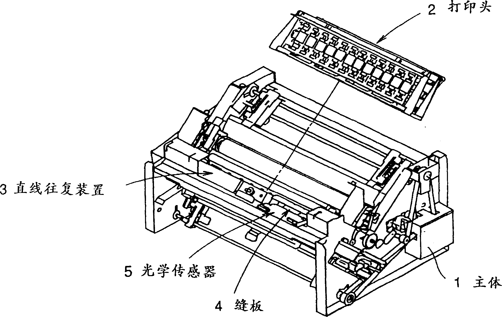
[0045] exist figure 1 A perspective view of the printing apparatus of the present invention is shown in .

[0046] exist figure 1 Among them, the print head 2 is mounted on the linear reciprocating device 3, and the linear reciprocating device 3 is movable in the left and right directions along the axis extending in the left and right direction of the printing device main body 1 (direction perpendicular to the conveying direction of the printing paper). device 3.

[0047] On the print head 2, a plurality of print head needles are arranged side by side in the left-right direction. For example, with 12 to 18 printhead pins. A yoke, a permanent magnet, and a slit plate 4 are arranged on the linear reciprocating device 3, and an optical sensor 5 composed of a pair of light-emitting LEDs and a photosensiti...


PUM


Abstract

In the printing dot shift correction control method of a printing apparatus performing printing by reciprocally moving a linear shuttle apparatus loaded with a printing head, a position detecting means for detecting the position data of the shuttle apparatus, a drive means driving the printing head so as to apply printing to paper and a control means for forming correction quantity for correcting the shift of a printing dot are provided. The control means forms the correction quantity corresponding to the acceleration or deceleration state of the shuttle apparatus when it is judged that the shuttle apparatus is in an acceleration or deceleration state during reciprocal movement from the position data detected by the position detecting means and controls the drive means on the basis of the correction quantity so that the drive means drives the printing head to a position same to a position where the printing head performs printing when the shuttle apparatus is in an equal speed state during reciprocal movement.

Description

technical field [0001] The present invention relates to a printing dot offset correction control method, in particular to a printing dot offset correction control method for correcting printing timing of a printing device with a linear reciprocating device to eliminate dot offset. Background technique [0002] A linear reciprocating device capable of printing multiple dots at a time by arranging a plurality of print heads in parallel is mounted on a high-speed printing device. [0003] At the time of printing, synchronously with the feeding of the printing paper contained in the main body of the printing device, the linear reciprocating device continuously repeatedly performs reciprocating motion in a direction perpendicular to the paper feeding direction. Since the linear reciprocating device continuously repeats the reciprocating motion, the speed of the linear reciprocating device changes in a sinusoidal manner as shown in FIG. 10 . [0004] Moreover, in order to detect ...

Claims


Application Information

Patent Timeline
Patent Type & Authority Patents(China)
IPC IPC(8): B41J2/515B41J2/51G06K15/00H04N1/04H04N1/23H04N1/40
CPCB41J2/2139B41J2/2142B41J2/51B41J2/515G06K15/002
Inventor 藤本博畑淳井上誠
Owner FUJIFILM BUSINESS INNOVATION CORP
Why Eureka
Try Eureka