Centrifuge comprising hydraulic differential speed determination

A centrifuge, fixed speed technology, applied in the field of centrifuges, can solve the problem of damage to the rotary joint, and achieve the effect of avoiding volume loss

Inactive Publication Date: 2006-05-10
VISCOTHERM AKTIENGES
View PDF1 Cites 2 Cited by
  • Summary
  • Abstract
  • Description
  • Claims
  • Application Information

AI Technical Summary

Problems solved by technology

Due to the large throughput of the high flow rate of the hydraulic liquid input at high pressure, the requirements for such a rotary joint are high, which is the flow and pressure requirements, so that the structural size and leakage of this problematic component sex in particular can cause problems
Although such a co-rotating hydraulic motor combines light weight, good adjustability and robustness, the swivel joints required by so far conceived are problematic for damage

Method used


Image

  • Centrifuge comprising hydraulic differential speed determination
  • Centrifuge comprising hydraulic differential speed determination
  • Centrifuge comprising hydraulic differential speed determination

Examples


Embodiment Construction

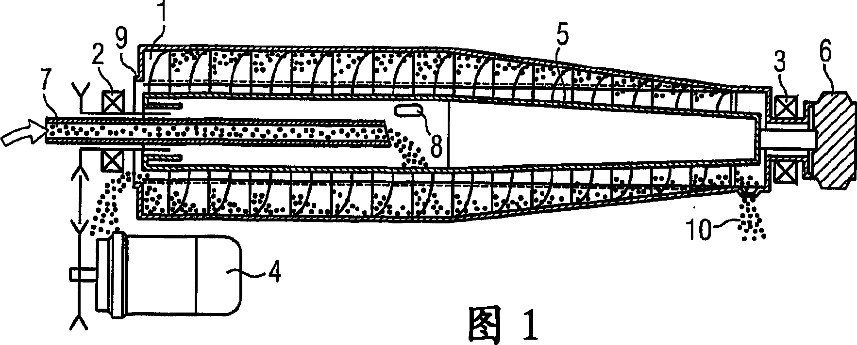
[0036]As shown in FIG. 1 , this machine generally comprises a drum 1 , which is rotated by means of bearings 2 and 3 and driven by a motor 4 ; a worm 5 coaxially located in the drum, said worm by means of a worm drive 6 Has a slightly different rotational speed than drum 5. Therefore, the worm rotates with a certain rotational speed difference relative to the drum. The product or solid-liquid mixture is fed via the outlet pipe 7 into the worm hub (Nabe), which reaches the separation chamber through the opening 8 and forms an annular pool here, the height of which is defined by the overflow protection 9 . The heavier phase (sediment) is deposited on the drum wall and is conveyed by the worm through the taper in the tank to the discharge opening 10, where it is thrown out.

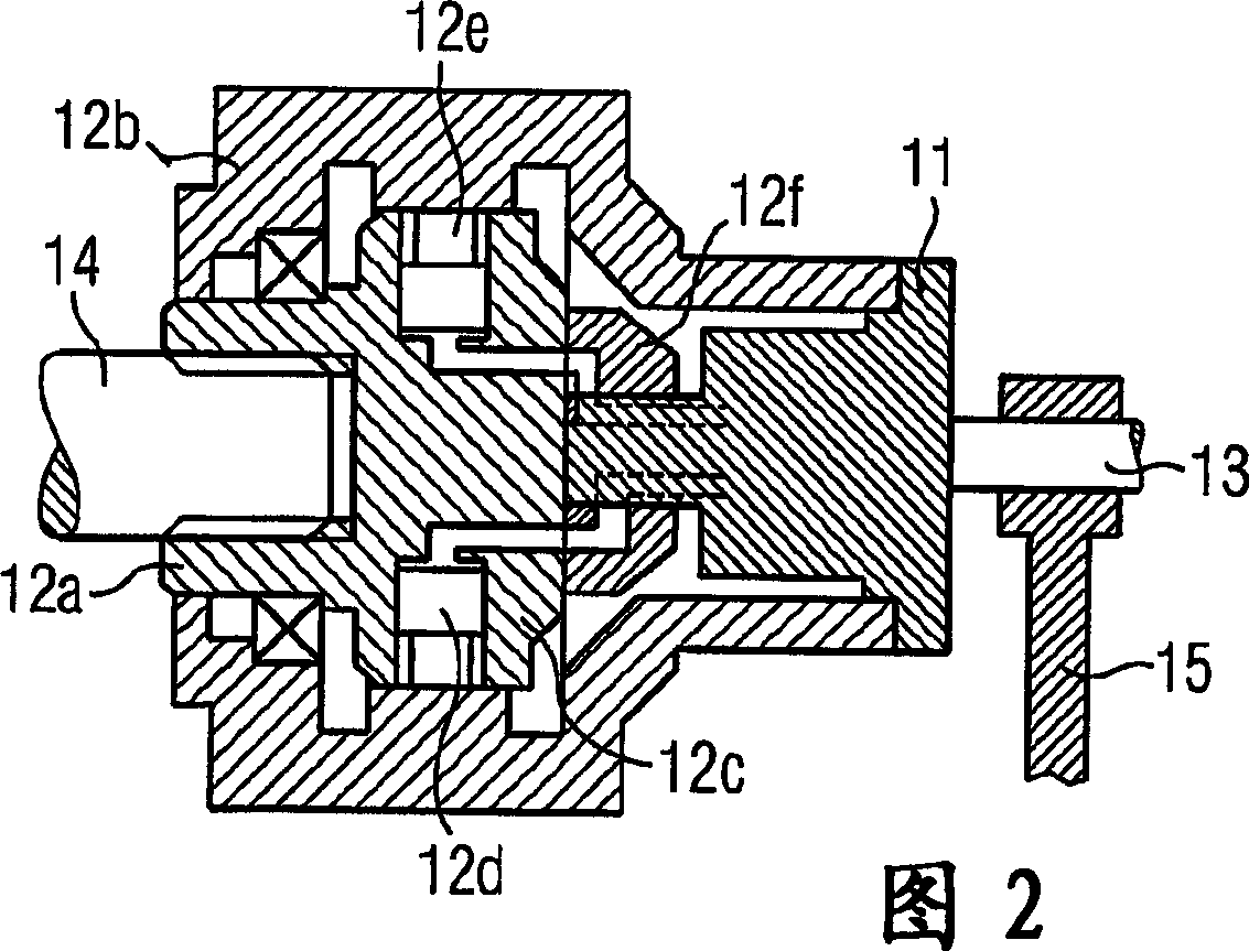
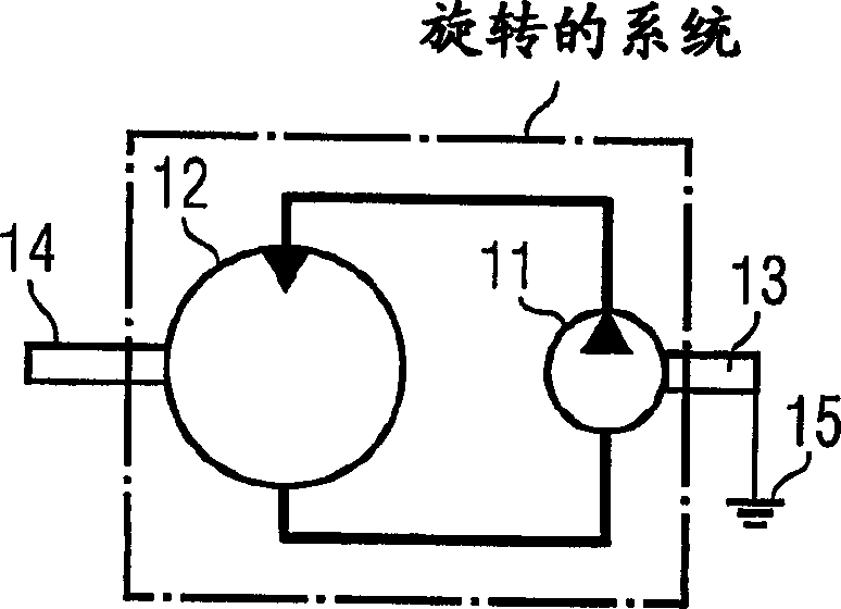
[0037] FIG. 2 shows a schematic diagram of such a drive. A multi-stroke radial piston machine is shown as an example of a high-torque hydraulic motor 12 . In its housing 12b, which is attached to the drum...


PUM


Abstract

The invention relates to a centrifuge comprising a rotationally mounted drum (1) and a worm (5) that is mounted therein in a concentric manner so as to rotate at a different speed therefrom. The drum (1) and the worm (5) are driven by a stationary motor unit (4; 22). A hydraulic motor (12; 21) which is provided with a housing (12b) and a rotor (12c) and is fed by means of a hydraulic pump (11; 23; 41) is mounted therebetween. Such a centrifuge is characterized by the fact that the hydraulic feed pump is assigned to the hydraulic motor (12; 21) so as to rotate along with said hydraulic motor (12; 21) while the rotor (13) thereof is supported (15) outside the rotating centrifuge parts in order not to rotate together with said rotating centrifuge parts. Additionally, the quantity of liquid delivered to the hydraulic motor (12, 21) by the feed pump (11, 23, 41) is modified via displacement members (42; 43; 29, 30) that are actuated in a hydraulic fashion and are disposed on the drive unit so as to rotate therewith.

Description

technical field [0001] The invention relates to a centrifuge with a rotatably mounted drum and a worm screw mounted centrally in the drum with a rotational speed difference, the drum and the worm screw being driven by a central external (fixedly mounted) motor device To drive, a hydraulic motor with its casing and its rotor is installed between the drum and the worm, as a transmission device that can determine the speed difference, and provides input to the hydraulic motor through a hydraulic pump. Background technique [0002] A centrifuge of the type mentioned at the outset is a centrifuge in which a transmission is connected between two parts rotating with a rotational speed difference, called drum and worm, and is based on a decanter centrifuge, here mainly illustrated. In particular decanter worm centrifuges, but also trommel decanters and full tank decanters (Vollteichdekanter). This also includes the number and type of phases of the solid-liquid mixture fed in that ...

Claims


Application Information

Patent Timeline
Patent Type & Authority Applications(China)
IPC IPC(8): B04B1/20F16H61/40F16H61/4052F16H61/42
CPCB04B1/2016F16H61/4052F16H61/42
Inventor S·U·坎宁安F·福斯特
Owner VISCOTHERM AKTIENGES
Why Eureka
Try Eureka