Semiconductor-laser-pumped solid-state laser apparatus

A solid-state laser and semiconductor technology, applied in the direction of lasers, laser parts, phonon exciters, etc., can solve the problems of large power consumption, uneconomical power consumption, etc., achieve safe driving current switching, reduce energy consumption, and improve reliability sexual effect

Inactive Publication Date: 2006-05-03
FANUC LTD
View PDF1 Cites 1 Cited by
  • Summary
  • Abstract
  • Description
  • Claims
  • Application Information

AI Technical Summary

Problems solved by technology

In the past, when the laser start signal from the external control device was turned off, even if the laser processing was not performed, as shown in FIG. -LD, so power is consumed even when laser processing is not performed
In addition, the life of a semiconductor laser is generally determined by the application time of the driving current. Therefore, when the laser processing is not performed, the driving current is also passed through the semiconductor laser, and its life will be shortened by as much as the power-on time, which is not economical.
[0008] Conventionally, as described above, the external control device 8 provided the start signal and the stop signal to the laser oscillation control unit 7, but when the laser is not oscillating, such as when the workpiece 9 is exchanged or the process schedule is changed, the external control device 8 is The laser oscillation control section 7 is not controlled, so even when the oscillation of the solid-state laser is stopped, the drive current I-LD between L-TH and LD-TH flows according to the program in the laser oscillation control section 7, so there is consumption The problem of high power and the problem of shortening the lifetime of the semiconductor laser 2

Method used


Image

  • Semiconductor-laser-pumped solid-state laser apparatus
  • Semiconductor-laser-pumped solid-state laser apparatus
  • Semiconductor-laser-pumped solid-state laser apparatus

Examples


Embodiment Construction

[0029] Embodiments of the semiconductor laser pumped solid-state laser according to the present invention will be described in detail below with reference to the drawings.

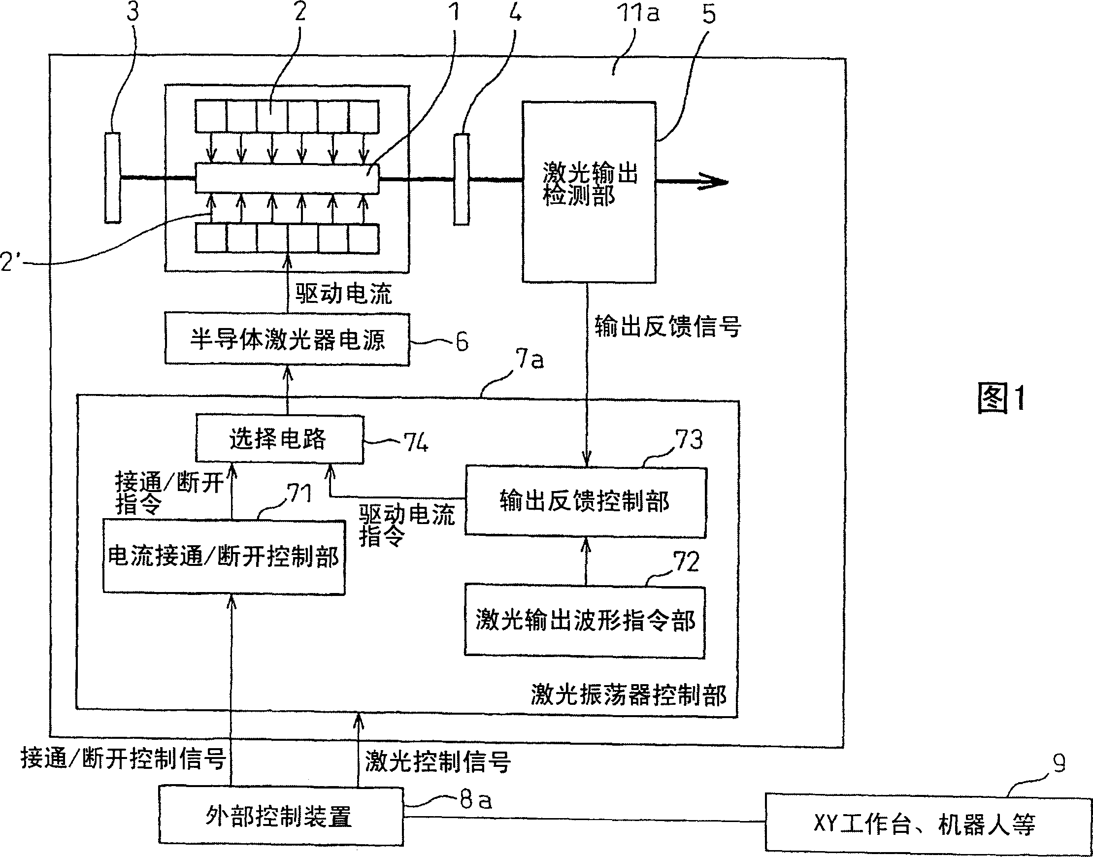
[0030] Fig. 1 is a block diagram showing the structure of a semiconductor laser pumped solid-state laser device according to Embodiment 1 of the present invention. In this figure, the structure of a semiconductor laser pumped solid-state laser device 11a is basically the same as that of the semiconductor laser pumped solid-state laser device 11 shown in FIG. 5, and the same reference numerals are attached to the same parts. In the present invention, the structure of the laser oscillation control unit 7a and the structure of the external control device 8 are different from those of the conventional ones.

[0031] The semiconductor laser excitation solid-state laser device of this embodiment has: a current on / off control unit 71 that outputs an on / off command signal based on an on / off control signal output f...


PUM


Abstract

The invention provides a semiconductor laser excitation solid-state laser device. In the semiconductor laser excitation solid-state laser device (11) for laser oscillation by using a semiconductor laser (2) to excite a solid-state laser medium (1), there is a control signal from the outside , switching the operation current of the above-mentioned semiconductor laser to the state of energizing at the oscillation threshold (L-LD) of the semiconductor laser or a current value above the threshold, and the driving current of the state of energizing at a current value smaller than the oscillation threshold of the semiconductor laser The switching unit (71) therefore can reduce the power consumption of the laser processing system and prolong the life of the semiconductor laser by controlling the laser oscillation control unit from the external control device even when the oscillation of the solid-state laser is stopped.

Description

technical field [0001] The present invention relates to a semiconductor laser excitation solid-state laser device, in particular to a semiconductor laser excitation solid-state laser device capable of controlling the driving current of the semiconductor laser by a signal from an external control device for controlling a laser processing system. Background technique [0002] We introduce laser processing systems in various fields such as cutting, welding, surface improvement, marking, and trimming of materials and parts. The laser device used in the laser processing system involves many aspects, but the semiconductor laser excitation solid-state laser device uses a semiconductor laser as a solid-state laser medium excitation light source, and is generally used to exert the characteristics of a single-wavelength oscillation and long-life semiconductor laser. Compared with the conventional lamp-excited solid-state laser device, the semiconductor laser-excited solid-state laser ...

Claims


Application Information

Patent Timeline
Patent Type & Authority Applications(China)
IPC IPC(8): H01S3/0941H01S3/131
CPCH01S3/0941H01S3/1312
Inventor 町田久忠吉田宏之高桥广光西川佑司
Owner FANUC LTD
Why Eureka
Try Eureka