Parallel-connected type light-emitting diode driving device

A technology of light-emitting diodes and driving devices, which can be used in instruments, static indicators, etc., and can solve problems such as power loss and power loss.

Inactive Publication Date: 2006-05-03
雅捷科技股份有限公司
View PDF0 Cites 10 Cited by
  • Summary
  • Abstract
  • Description
  • Claims
  • Application Information

AI Technical Summary

Problems solved by technology

The existing driving circuit is to give a large voltage value regardless of the number of light-emitting diodes in the circuit and the required voltage, but this will cause serious power loss. figure 1 It is a schematic diagram of an existing parallel-connected light-emitting diode driving device, wherein a power supply device 10 (such as a battery) provides a voltage to the driving circuit 11, and the output of the driving circuit is respectively provided to three light-emitting diode units 12, 13, and 14, and the above-mentioned The diode units 12, 13, and 14 require different driving voltages, but generally a maximum voltage value is given. The diode unit 14 has three light-emitting diodes, so this circuit provides a voltage of 10 volts to the diode unit 14 and the number of diodes. Fewer diode units 12, 13, so there is a large amount of power loss in the above-mentioned diode units 12, 13

Method used


Image

  • Parallel-connected type light-emitting diode driving device
  • Parallel-connected type light-emitting diode driving device
  • Parallel-connected type light-emitting diode driving device

Examples


Embodiment Construction

[0009] In order to better understand the technical content of the present invention, a preferred specific embodiment is given as follows.

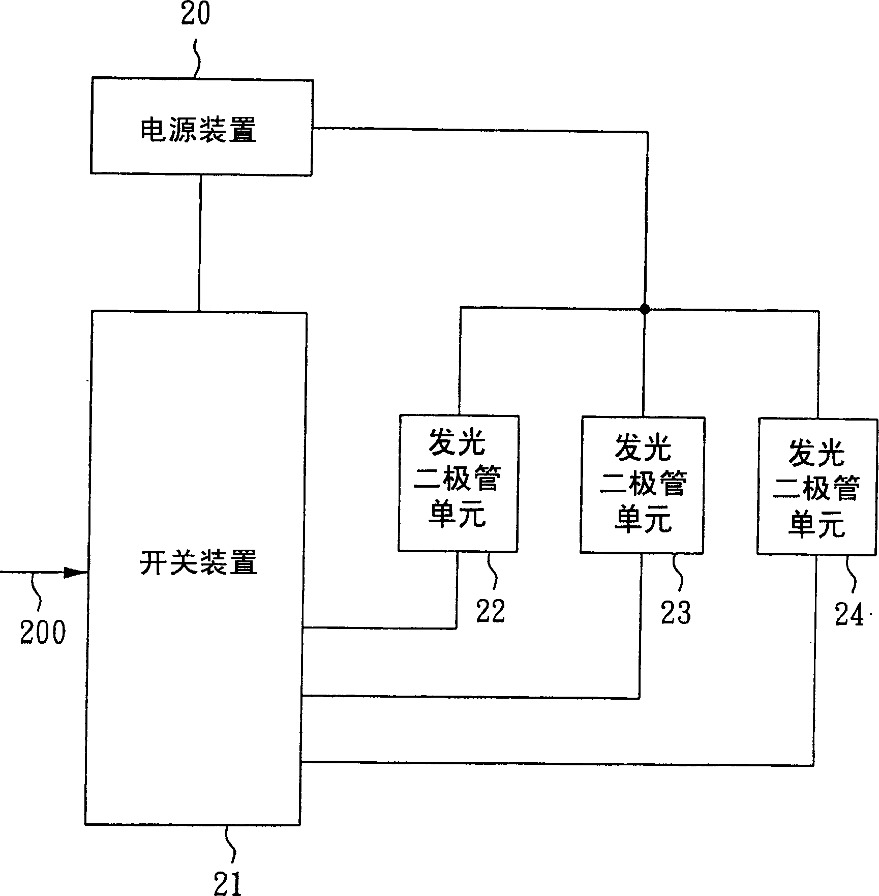
[0010] figure 2 It is a schematic diagram of a preferred embodiment of the present invention. In this example, three sets of light-emitting diode units 22, 23., 24 are connected in parallel, but it should not be limited to this, and two, four, or even more sets can also be connected in parallel. LED unit. figure 2 Among them, this example is a parallel LED driving device, including three groups of LED units 22, 23, 24, which are powered by a power supply device 20, and are respectively connected to the selection switch 21, and the switching device 21 is based on the input A group of control signals 200 respectively switch whether the three groups of LED units 22, 23, 24 are on or off.

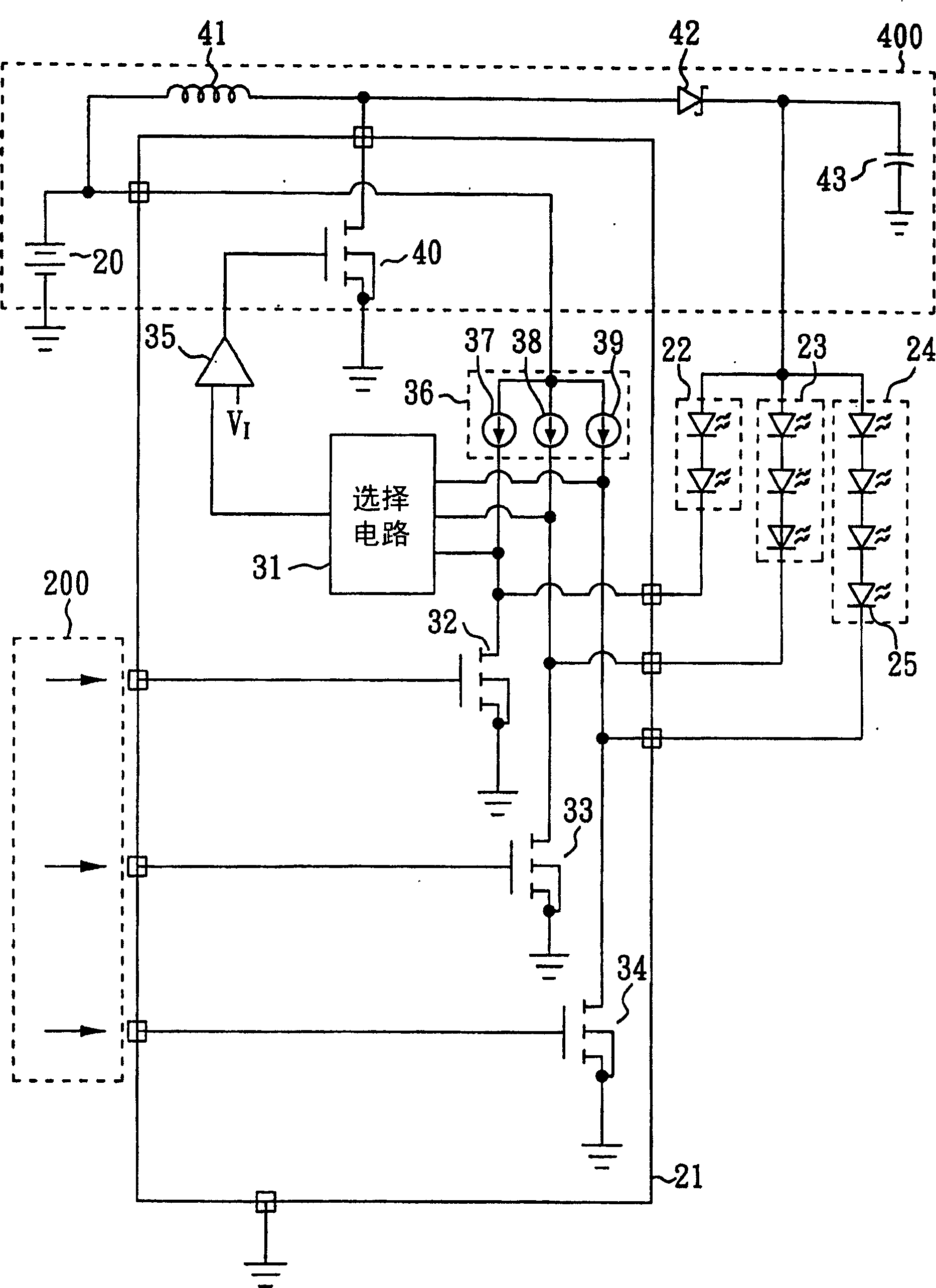
[0011] image 3 It is a system architecture diagram of a preferred embodiment of the present invention. In the figure, the light-emitting diode unit 2...


PUM


Abstract

The invention relates to a parallel light-emitting diode driver which comprises a switch, a power and a plurality of groups of light-emitting diode units, wherein it uses the switch to parallel the plurality of groups of light-emitting diode units so that the power can provide the electricity to the light-emitting diode.

Description

technical field [0001] The invention relates to a light-emitting diode driving device, especially a high-efficiency parallel-connected light-emitting diode driving device. Background technique [0002] The display function is very important in products such as personal digital assistants (PDA), mobile phones (Cell Phone), digital cameras, video recorders, etc. Most of these products use a large number of white light diodes (White LED) and red Light, green light, and blue light diodes (Color R-RED, G-Green, B-B1L1e LED), so the production of these light-emitting diodes is very important for the above-mentioned digital products. [0003] At this stage, many products need to use different types of light-emitting diode combinations. For example, the red light diode is 1.9 volts, and the green and blue light diodes are 3.7 volts. The driving circuit is used to control whether numerous light-emitting diodes emit light or not. The existing driving circuit is to give a large volta...

Claims


Application Information

Patent Timeline
Patent Type & Authority Applications(China)
IPC IPC(8): G09G3/14
Inventor 曾昭隆索灵劳伦提尼各鲁
Owner 雅捷科技股份有限公司
Why Eureka
Try Eureka