
Plasma display assembly

A plasma display and component technology, applied in the field of invention of plasma display components, can solve the problems of increased power, complex structure, heating of the circuit and the like

Inactive Publication Date: 2006-05-03
NANJING LG TONGCHUANG COLOR DISPLAYS SYST CO LTD
View PDF0 Cites 3 Cited by
  • Summary
  • Abstract
  • Description
  • Claims
  • Application Information

AI Technical Summary

Problems solved by technology

[0038] However, since the existing 1st and 2nd energy recovery circuits 32.34 are separately arranged as the Y maintaining plate 46 and the Z maintaining plate 48, many circuit parts (switching elements, etc.) are required, and the required power increases accordingly.
Therefore, the structure of the existing PDP module is relatively complicated and the manufacturing cost is relatively high.
In addition, each component of the existing first and second energy recovery loops 32.34 will generate heat, especially the heat dissipation of the inductor coil is relatively serious, which has the disadvantage of heating the loop

Method used


Image

  • Plasma display assembly
  • Plasma display assembly
  • Plasma display assembly

Examples


Embodiment Construction

[0083] Refer to the following Figure 9 to Figure 14 Embodiments of the plasma display unit of the present invention will be described in detail.

[0084] Figure 9 is a schematic diagram of a plasma display according to an embodiment of the present invention; Figure 10 is like Figure 9 Schematic diagram of the cross-sectional configuration of the plasma display assembly shown.

[0085] Figure 9 and Figure 10 The composition of the PDP assembly shown includes: a heat release pipe 86 arranged on the back of the PDP70; a Y-Z integrated board 100 arranged on the back of the heat release pipe 86; a data driver board 80; a control board 72; A power board (not shown in the figure) of the power supply; a transmission printed circuit board (Printed Circuit Board: PCB for short).

[0086] In the PDP 70, the front glass plate 90 and the rear glass plate 92 have a gas discharge space and have a connected structure. Here, in the front glass plate 90 such as figure 2 As shown,...


PUM


Abstract

The invention relates to a plasma display assemble which comprises: a plasma display comprising a scanning electrode wire and a holding electrode wire, a holding plate providing Y holding impulse to the scanning electrode wire and the Z holding impulse to the holding electrode wire, a channel printing circuit plate which is formed by connecting the sensor with the holding plate and the holding electrode wire.

Description

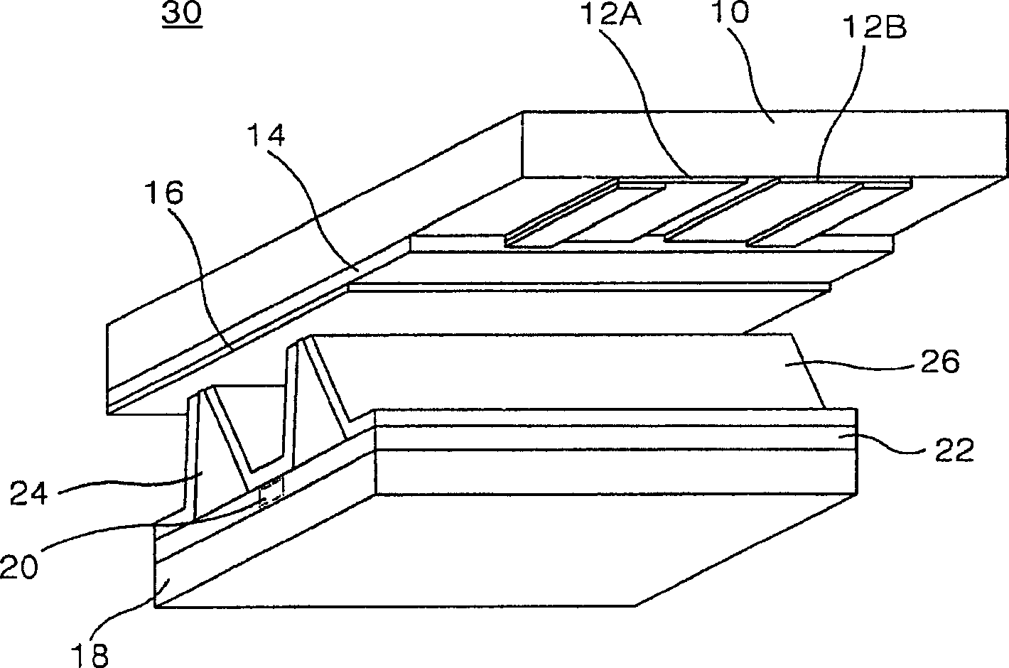
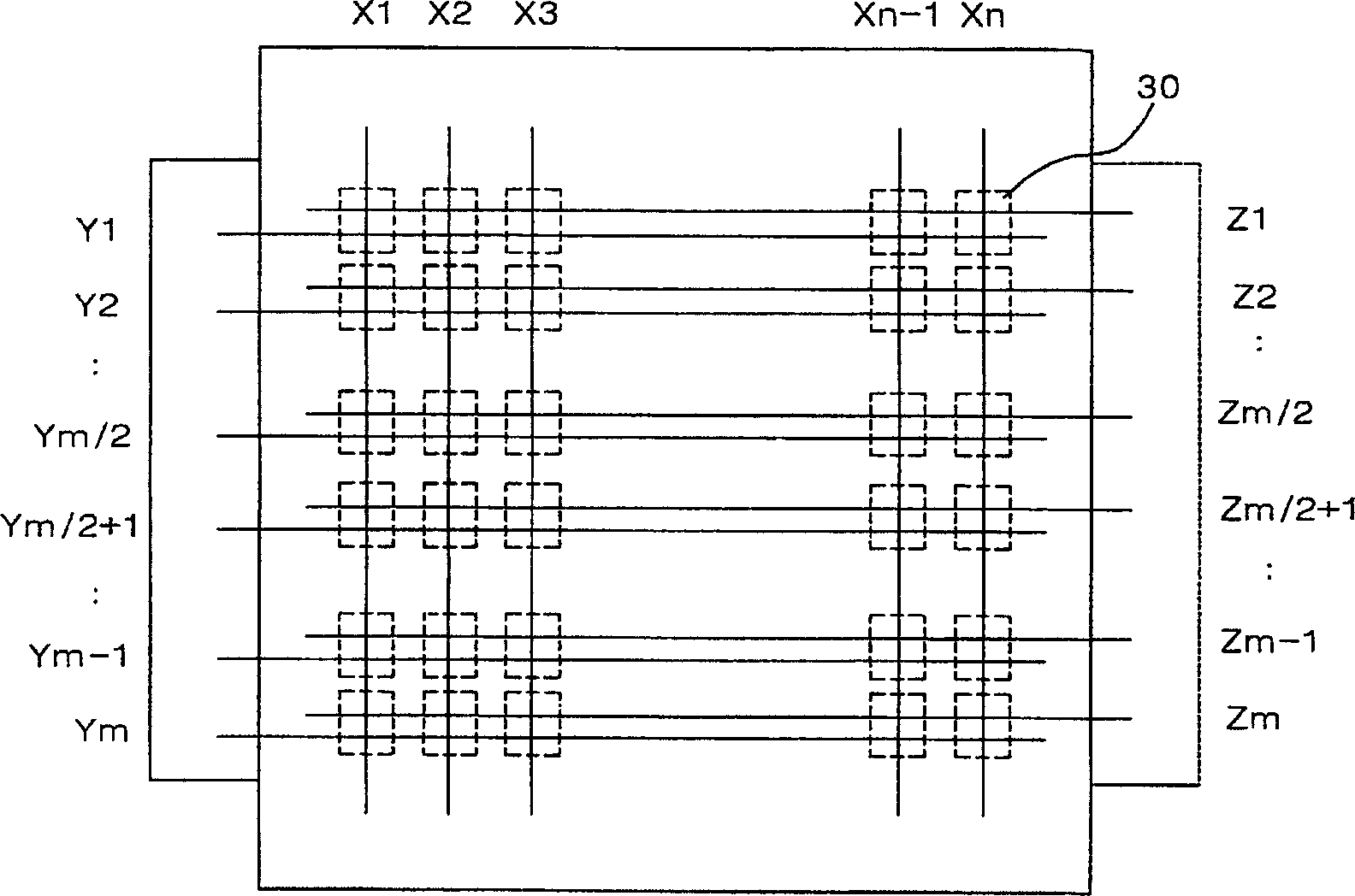
(1) Technical field [0001] The present invention relates to the technology of the plasma display assembly, in particular to the invention of a plasma display assembly which can effectively prevent circuit heating while integrating the maintenance board. (2) Background technology [0002] Recently, as a flat-panel display, a plasma display PDP (Plasma Display Panel, hereinafter referred to as PDP), which is easy to manufacture into a large screen, is attracting more and more attention. PDPs usually display images by adjusting the individual discharge times of pixels through digital video data. As such a PDP, the same as figure 1 It is shown that an AC-type PDP that has three electrodes and is driven by an AC voltage is more representative. [0003] figure 1 It is a schematic diagram of one discharge unit body constituting a conventional AC type PDP. [0004] Such as figure 1 The discharge unit body 30 shown is mainly composed of a front glass plate and a rear glass plate,...

Claims


Application Information

Patent Timeline
IPC IPC(8): G09F9/313G09G3/28
Inventor 崔正泌
Owner NANJING LG TONGCHUANG COLOR DISPLAYS SYST CO LTD
Learn More