
DC excursion correcting device

A DC offset and correction device technology, which is applied in the direction of improving amplifiers to reduce temperature/power supply voltage changes, etc., can solve the problems of circuit cost increase, voltage-type digital resolution limitation, and the inability to simultaneously reduce circuit cost and correction accuracy, etc.

Inactive Publication Date: 2006-04-26
MEDIATEK INC
View PDF0 Cites 13 Cited by
  • Summary
  • Abstract
  • Description
  • Claims
  • Application Information

AI Technical Summary

Problems solved by technology

[0006] However, the aforementioned method of improving the accuracy of DC offset correction will not only increase the cost of the circuit, but also the accuracy of the correction is still limited by the resolution of the voltage-type digital-to-analog converter used.
In other words, the known technology obviously cannot meet the dual requirements of reducing circuit cost and improving calibration accuracy at the same time

Method used


Image

  • DC excursion correcting device
  • DC excursion correcting device
  • DC excursion correcting device

Examples


Embodiment Construction

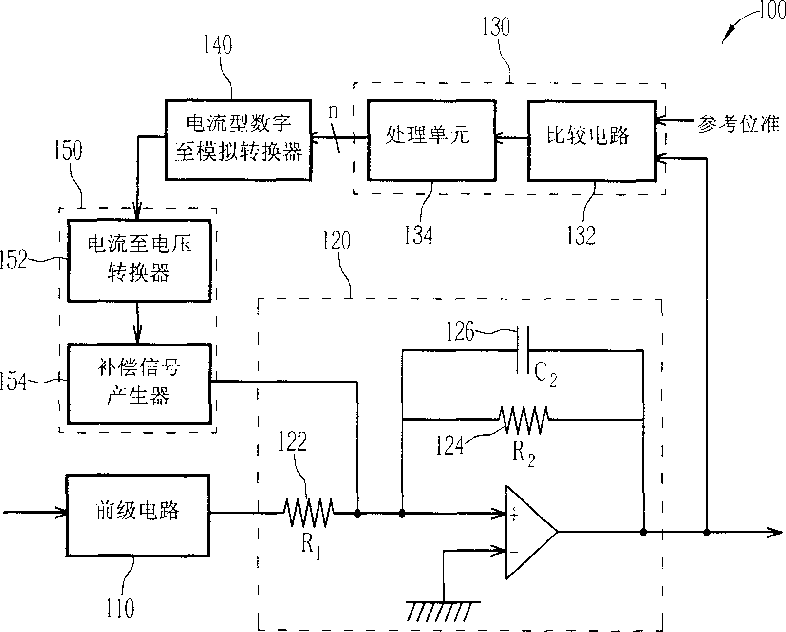
[0034] The DC offset correction device proposed by the present invention, in addition to being applicable to signal receivers (receivers) or transmission receivers (transceivers) of direct conversion architecture or superheterodyne architecture, can also be applied to other Electronic circuit for DC offset. For the convenience of description, the structure and operation of the DC offset correction device of the present invention will be described below by taking a radio frequency signal receiver using the DC offset correction device of the present invention as an example. It should be noted that the embodiments disclosed below are intended to illustrate rather than limit the scope of application of the present invention.

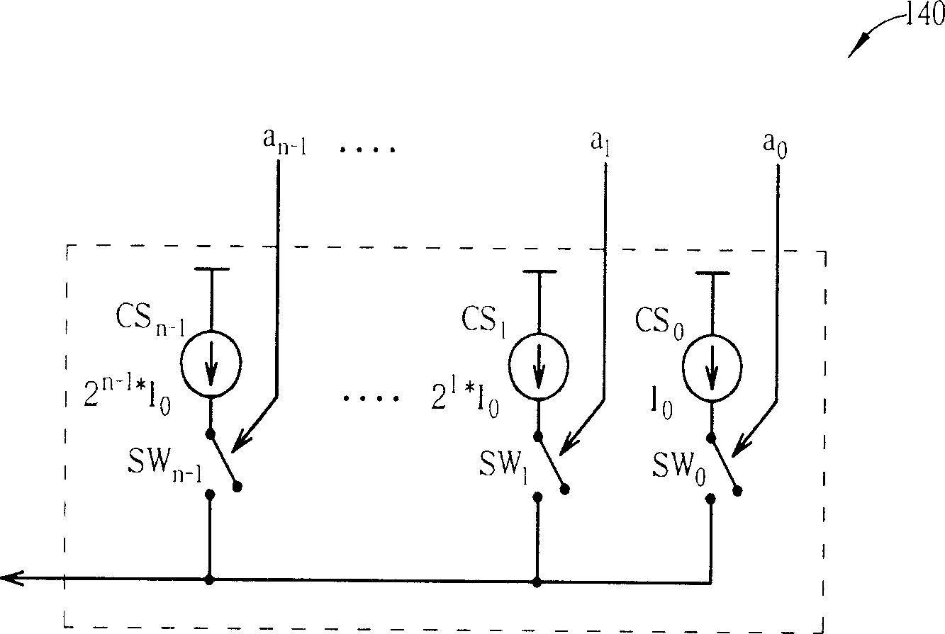
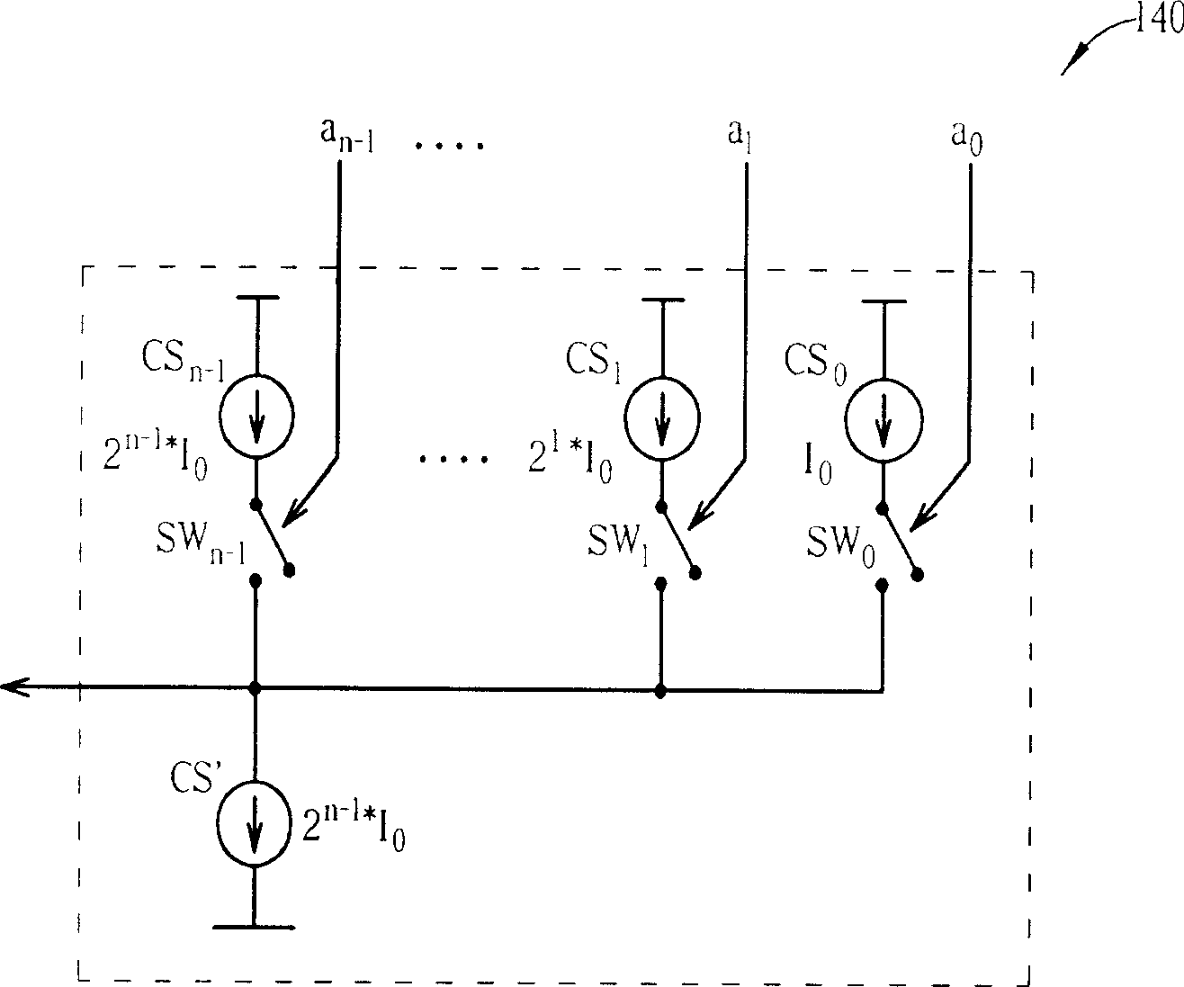
[0035] Please refer to figure 1 , which is a simplified partial block diagram of a signal receiver (receiver) 100 applying the DC offset correction device of the present invention. The signal receiver 100 includes a pre-stage circuit 110 and a gain stage 1...


PUM


Abstract

The invention provides a DC offset correction device for output signal of gain stage, which comprises: a DAC electric connected to gain stage to generate a current signal according to output DC offset, a current-to-current converter electric connected to the DAC and gain stage to compression treat the current signal to generate a compensation signal and reduce said DC offset.

Description

technical field [0001] The invention provides a DC offset correction device, especially a correction device for reducing the DC offset of a circuit. Background technique [0002] In the past wireless communication applications, most radio frequency transmission receivers (RFtransceiver) adopt the traditional "super-heterodyne" (super-heterodyne) architecture. Although the superheterodyne transmission receiver has good performance, it must use many components such as expensive and bulky intermediate frequency surface acoustic wave filter (IF SAW Filter), which makes the system complexity and production cost higher. [0003] Recently, many radio frequency transmission receivers adopt a "direct conversion" type architecture to improve the above-mentioned problems of the superheterodyne transmission receiver. Direct conversion is also called zero intermediate frequency (zero IF), which directly reduces the received radio frequency signal to the base frequency. Compared with th...

Claims


Application Information

Patent Timeline
Patent Type & Authority Applications(China)
IPC IPC(8): H03F1/30
Inventor 屈庆勋沈致贤王守琮邱继昆
Owner MEDIATEK INC
Learn More