
Method for operating a hybrid vehicle

A hybrid vehicle and vehicle technology, which is applied to hybrid vehicles, motor vehicles, electric vehicles, etc., can solve problems such as reducing efficiency, and achieve the effects of reducing emissions, reducing fuel consumption, and reducing NOx emissions.

Inactive Publication Date: 2006-04-12
AVL LIST GMBH
View PDF4 Cites 14 Cited by
  • Summary
  • Abstract
  • Description
  • Claims
  • Application Information

AI Technical Summary

Problems solved by technology

Reduced efficiency in the lower part load range is a disadvantage

Method used


Image

  • Method for operating a hybrid vehicle
  • Method for operating a hybrid vehicle
  • Method for operating a hybrid vehicle

Examples


Embodiment Construction

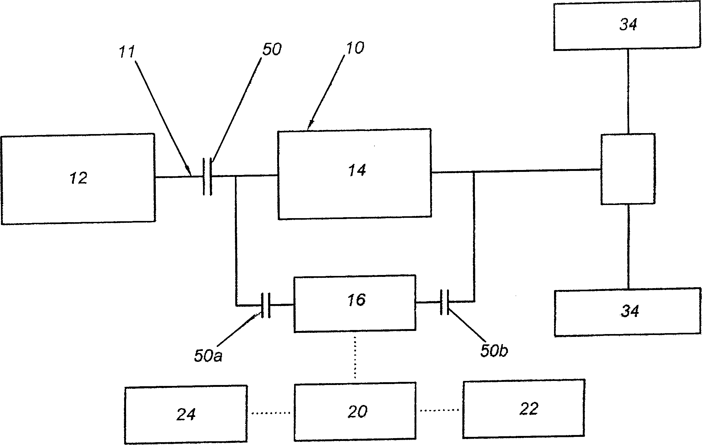
[0026] figure 1 shows the overall structure of the hybrid powertrain 10 . The hybrid driving source in the drive train 11 is a diesel engine 12 , which is reduced relative to a reference power, connected to be actuated in an automated manner with an automatic transmission 14 having eg 6 gears through a clutch 50 . The electric drive mechanism 16 is connected to the automatic transmission 14 by engaging and disengaging clutches 50a, 50b, such as engaging and disengaging synchronized clutches. The electric drive mechanism 16 operates either as a generator or as an electric motor, with a constant output power of about 10 kW in the embodiment, and a peak output power of about 25 kW for 5 seconds. It is triggered by the power electronics 20 via a battery voltage 22 of 12V and via a double layer capacitor 24 of 42V. The electric drive 16 is connected on the one hand to the drive shaft 30 and on the other hand to the output shaft 32 of the automatic transmission via an intermediate...


PUM


Abstract

The invention relates to a method for operating a hybrid vehicle with a drive train which comprises an internal combustion engine driven by diesel fuel and at least one electric driving machine. In order to reduce the nitrogen oxide and exhaust particulate emissions it is provided that the internal combustion engine is operated with an alternative diesel combustion method in at least one operating range of the vehicle and the electric driving machine is switched in.

Description

technical field [0001] The invention relates to a method for operating a hybrid vehicle with a drive train, comprising an internal combustion engine powered by diesel fuel and at least one electric drive, and a hybrid vehicle for carrying out the method. Background technique [0002] A hybrid vehicle comprising a diesel engine and at least one electric drive is known from JP 2003-065099 A or EP 1007 383 B1. In order to ensure that the internal combustion engine runs with the lowest possible emissions and the simplest possible means, EP 1007 383 B1 proposes, for example, that the hybrid drive control unit determine the time average value of the drive torque in each predetermined time period, the internal combustion engine The power output and the three-phase mechanism are controlled in such a way that the internal combustion engine outputs the drive torque in response to a determined average value over time, and the three-phase mechanism outputs the difference between the cur...

Claims


Application Information

Patent Timeline
Patent Type & Authority Applications(China)
IPC IPC(8): B60W20/00B60K6/02B60K6/48B60K6/547
CPCB60W20/00Y02T10/6286Y02T10/54B60Y2300/476B60W10/06B60K6/48F02D41/3035B60K6/547B60W10/08Y02T10/6221Y02T10/40Y02T10/62B60W20/15
Inventor R·伊灵格W·克里格勒M·威斯贝克P·伊贝纳
Owner AVL LIST GMBH
Learn More