Connector for memory card

A technology for memory cards and connectors, which is applied in the direction of connection, parts and instruments of connection devices, etc., to achieve the effects of easy production, increased locking force, and increased strength

Inactive Publication Date: 2006-04-05
MITSUMI ELECTRIC CO LTD
View PDF1 Cites 3 Cited by
  • Summary
  • Abstract
  • Description
  • Claims
  • Application Information

AI Technical Summary

Problems solved by technology

[0011] Here, the object of the present invention is to: solve the technical problem of preventing the memory card from flying out when the card is taken out, and reliably performing the memory card locking when the card is locked.

Method used


Image

  • Connector for memory card
  • Connector for memory card
  • Connector for memory card

Examples


Embodiment

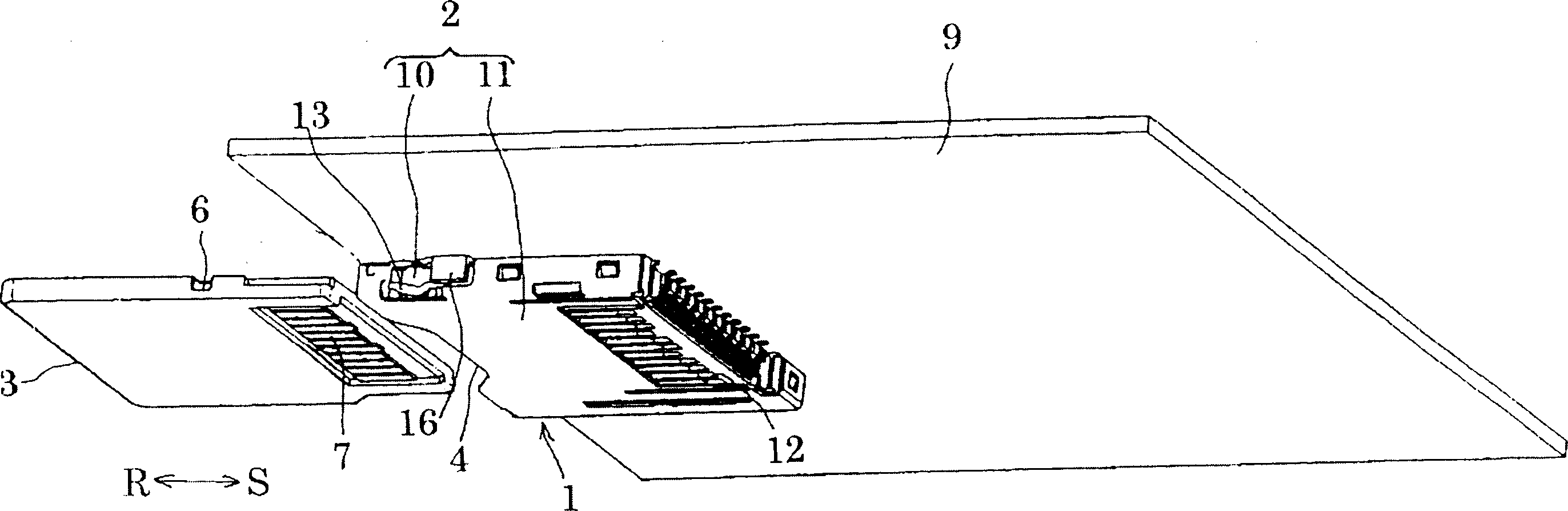
[0046] Below, refer to Figure 1 to Figure 12 Embodiments of the present invention will be described. figure 1 Among them, 1 is a connector for a memory card in a flat box shape, and an opening 4 for inserting and removing a memory card 3 is formed on the front of the housing 2 of the connector 1 . The above-mentioned memory card 3 is a small SD card, an xD picture card, etc. used in information equipment such as a digital camera or a mobile phone.

[0047] While the recessed portion 5 is formed on one end face of the memory card 3 in the width direction, a notched recess portion 6 is formed on the other end face of the memory card 3 in the width direction. In addition, a plurality of terminal portions 7 extending parallel to each other are formed on the back side in the insertion direction S of the memory card 3 .

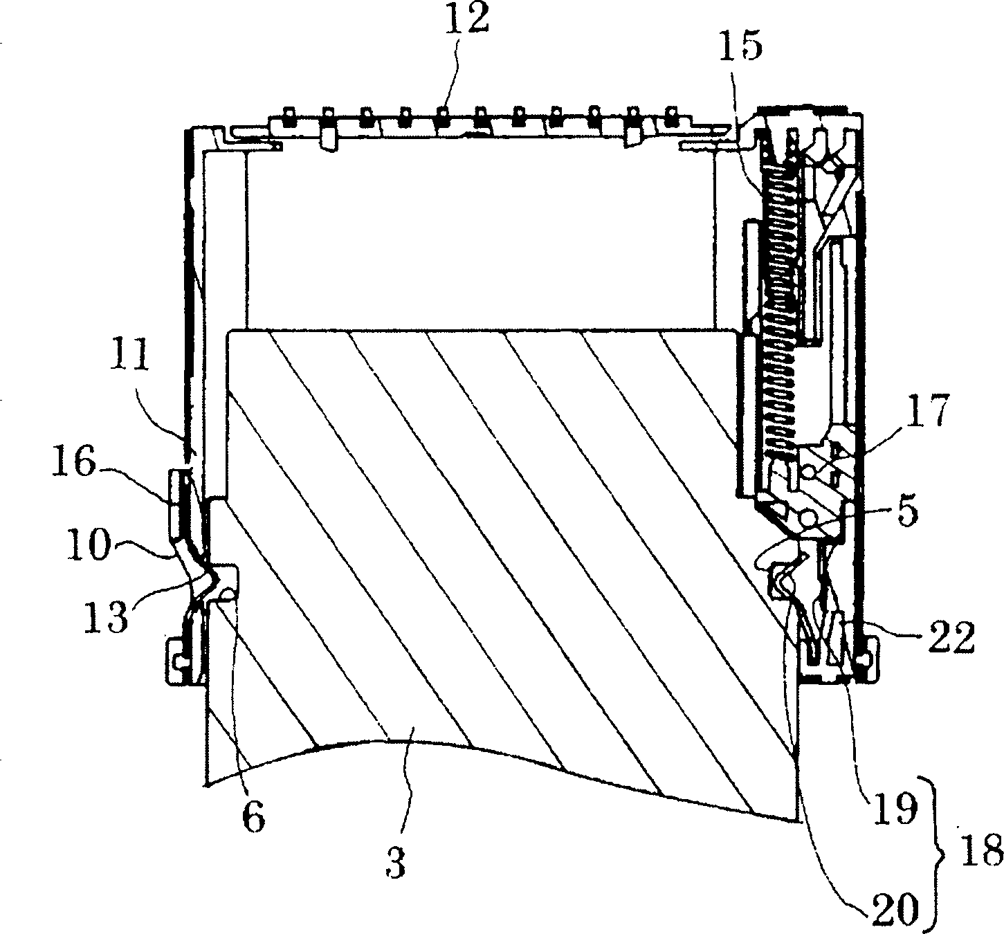
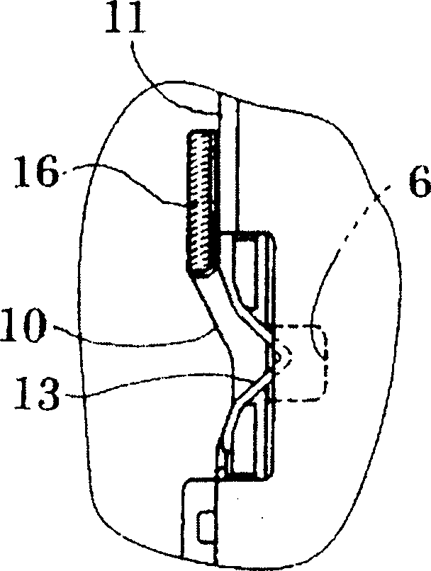
[0048] The housing 2 is composed of a resin bracket 10 fixed to a substrate 9 and a metal sealing plate 11 covering the bracket 10 . And, on the rear part of t...


PUM


Abstract

PROBLEM TO BE SOLVED: To prevent the falling-off of a memory card when the card is inserted to be locked, and to prevent the popping-out of the memory card when the card is ejected. ŽSOLUTION: A half-lock spring 18 is fixed to a slider 17 that is biased by a return spring 15 in the direction of card ejection. An engaging projection 20 engaged to the recess 5 of the memory card 3 is formed. On the inner-wall surface of a housing 10, there are provided inclined rib 22 for preventing the popping-out of the memory card 3 by the return spring when card is ejected, and a spring push lib 24 for preventing the falling-off of the memory card 3 when the card is inserted to be locked. Ž

Description

technical field [0001] The present invention relates to a connector for a memory card, and more particularly to a connector for a memory card provided with a half-lock mechanism for holding a memory card in a half-lock state. Background technique [0002] In the past, as this kind of memory card connector, it is well known that it has a slider installed inside the housing and can be freely installed forward and backward, and a half lock spring installed on the slider, and a lock spring is formed at the end of the half lock spring. Match the convex part. When the memory card is inserted into the housing, the concave portion on the side of the memory card cooperates with the matching protrusion of the half-lock spring to keep the memory card in a half-lock state. [0003] When the above-mentioned memory card is pushed in the half-lock state, the slider moves to the forward position against the elastic force of the return spring. At this time, the pin installed on the housing...

Claims


Application Information

Patent Timeline
IPC IPC(8): H01R12/16H01R12/24H01R13/629H01R13/639G06K17/00
Inventor 筒井敬贵高木庄一
Owner MITSUMI ELECTRIC CO LTD
Why Eureka
Try Eureka