
Rotor of wheel spoke type electric motor and its manufacturing method

A manufacturing method and motor technology, applied in the manufacture of stator/rotor bodies, etc., can solve problems such as difficulty in fixing, and achieve the effects of reducing production costs, increasing magnetic flux density, and reducing costs

Inactive Publication Date: 2006-03-29
LG ELECTRONICS (TIANJIN) APPLIANCES CO LTD
View PDF0 Cites 4 Cited by
  • Summary
  • Abstract
  • Description
  • Claims
  • Application Information

AI Technical Summary

Problems solved by technology

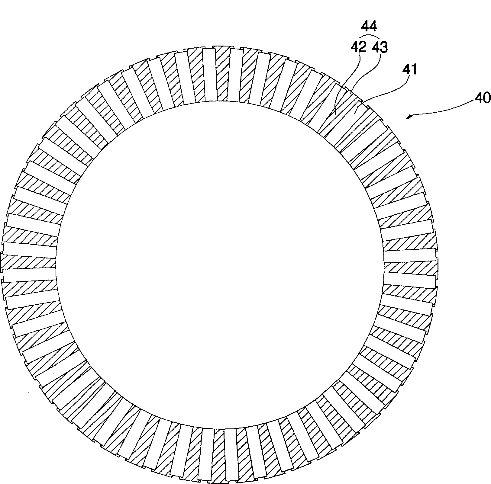
[0013] However, the rotor T-shaped column 44 and the permanent magnet 41 are formed by dividing the center portion in the circumferential direction, so it is difficult to fix them.
In addition, in order not to generate a leaking magnetic flux at the central portion of the rotor 40, other components need to be installed between the rotor T-shaped post 44 and the permanent magnet 41, resulting in the need to use more manufacturing processes.

Method used


Image

  • Rotor of wheel spoke type electric motor and its manufacturing method
  • Rotor of wheel spoke type electric motor and its manufacturing method
  • Rotor of wheel spoke type electric motor and its manufacturing method

Examples


Embodiment Construction

[0042] In order to further understand the invention content, characteristics and effects of the present invention, the following examples are given, and detailed descriptions are as follows in conjunction with the accompanying drawings:

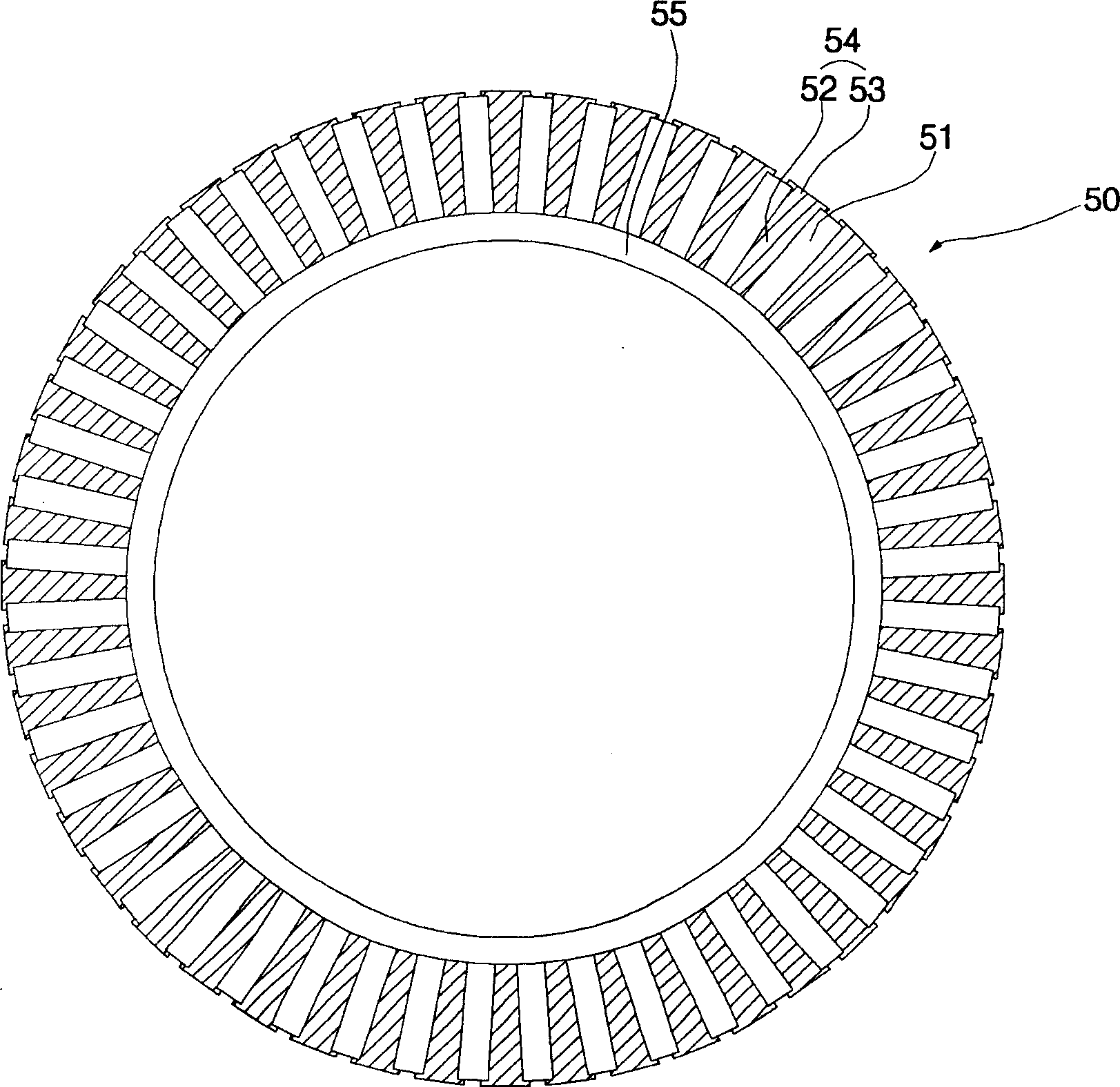
[0043] image 3 Fig. 1 is a sectional view of the spoke motor rotor according to the first embodiment of the present invention.

[0044] Utilize the rotor of the spoke type electric motor of first embodiment of the present invention, be by comprising that the center has annular non-electric conductor yoke ring 55; T-shaped pillars 54 ; and a plurality of permanent magnets 51 between adjacent rotor T-shaped pillars 54 .

[0045] The rotor T-shaped column 54 includes a radial rod 52 from the center direction of the rotor; and on the outer end side of the rod 52, a rod tail 53 forming a flange in the circumferential direction is formed, and the end face of the entire rotor T-shaped column is T-shaped.

[0046] Between adjacent rods 52 and rods...


PUM


Abstract

This invention relates to rotors of a spoke-like motor and its manufacturing method including a stator, multiple T shape posts installed radially in the stator and mutually isolated in gaps with the stator to the peripheral direction and rotors plug with permanent magnets installed among the posts, in which, a non-magnetic yoke is connected with one side of the multiple posts on the central part of the rotor and the rotor of a spoke like motor is manufactured by a screw method to stop part of the magnetic beam passing through the yoke to increase the beam density between the stator and the rotor to increase the moment.

Description

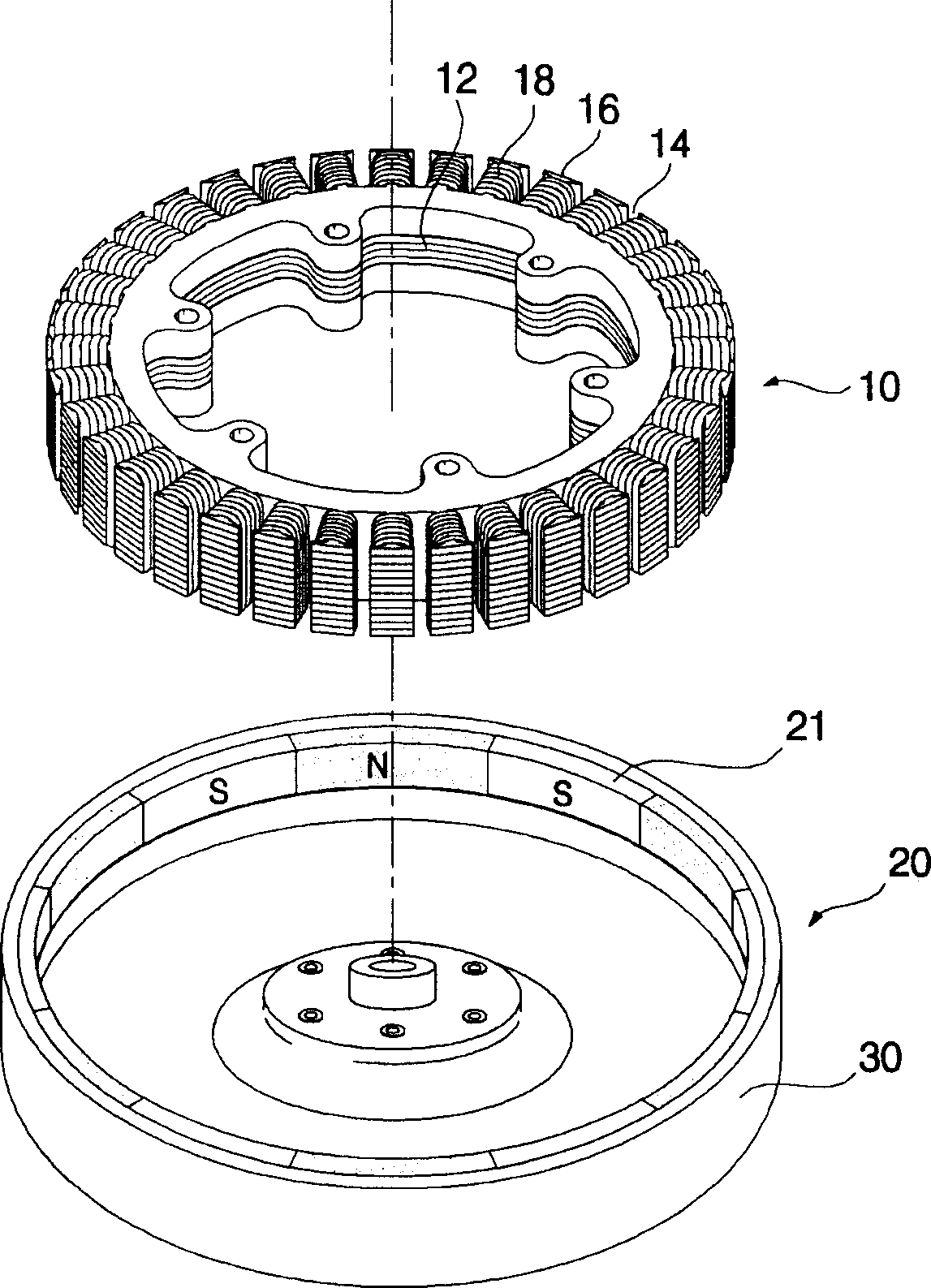
technical field [0001] The present invention relates to a rotor of a hub-spoke motor and a manufacturing method thereof. In particular, it relates to a spoke-type motor rotor and a manufacturing method thereof, which can improve the performance of the motor and improve the mounting performance of the rotor by installing a non-magnetic yoke in the spoke-type motor. Background technique [0002] In general, in the magnetic field of the motor, the conductor and the magnetic field are placed vertically. If the current passes through, the electronic induction phenomenon that generates the rotational force in the vertical direction of the magnetic field is used. According to the type of power supply, it is divided into DC motor and AC motor. [0003] figure 1 It is an exploded schematic diagram of an old-fashioned DC drive motor for washing machines using conventional technology. figure 2 It is a sectional view of the rotor of the spoke motor. [0004] The old-fashioned DC dri...

Claims


Application Information

Patent Timeline
IPC IPC(8): H02K15/02
Inventor 金德镇朴镇洙金永宽李成浩
Owner LG ELECTRONICS (TIANJIN) APPLIANCES CO LTD
Learn More