
Adaptive impedance relay

An impedance relay, self-adaptive technology, applied in the direction of electrical components, emergency protection circuit devices, protection that responds to fault currents, etc., can solve problems such as poor resistance to transitional resistance

Inactive Publication Date: 2006-03-29
CHANGSHA UNIVERSITY OF SCIENCE AND TECHNOLOGY
View PDF0 Cites 2 Cited by
  • Summary
  • Abstract
  • Description
  • Claims
  • Application Information

AI Technical Summary

Problems solved by technology

[0003] The technical problem to be solved by the present invention is to propose an adaptive impedance relay in view of the defects in the prior art, which has good adaptability to the grounding resistance, so as to overcome the failure of the existing impedance relay when a fault occurs in the protection zone. The problem of poor resistance to transition resistance

Method used


Image

  • Adaptive impedance relay
  • Adaptive impedance relay
  • Adaptive impedance relay

Examples


Embodiment Construction

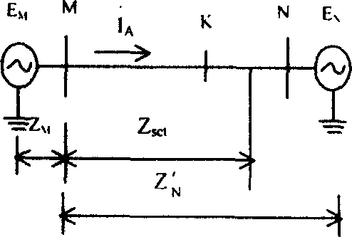
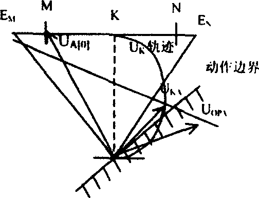
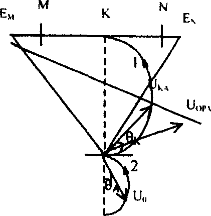
[0025] MATLAB software is used to simulate and calculate a 300Km long 500KV EHV line when phase A is grounded, and the transmission line adopts a distributed parameter model. System wiring such as figure 1 As shown, the simulation system parameters are as follows:

[0026] System parameters: Z M = Z N =5.74+j14.1Ω

[0027] Line parameters: r 1 = 0.02083Ω / km, l 1 = 0.8984mH / km, c 1 =0.0129MF / km

[0028] r 0 =0.1148Ω / km, l 0 =2.2886mH / km, c 0 = 0.00523 MF / km. The phase difference of the power supply potential on both sides of the line is 60°, and the setting area is 85% of the total length of the line.

[0029] Simulation calculation content: simultaneously polarize the zero-sequence voltage ( 0 ) and the commonly used memory voltage polarization ( A[0] ), positive sequence voltage polarization ( A1 ), the sudden change of working voltage phase (that is,  OP[0] Polarization) for the phase simulation of the action characteristics of the ground impedan...


PUM


Abstract

This invention relates to an earth faulty distance protection technology of high voltage transmission line, which is an adaptive earth direction impedance relay taking the residual voltage Uo at the faulty protection installation place as the polarized volume, which not only has the strong ability of bearing the transient impedance, but also has the advantage of protecting residual component.

Description

technical field [0001] The invention relates to a high-voltage transmission line grounding fault distance protection technology. Background technique [0002] The most common fault in high-voltage transmission lines is single-phase grounding. How to increase the allowable transition resistance during ground faults in the protected area and how to ensure clear directionality are important issues for grounding directional impedance relays. Due to the existence of the transition resistance, the traditional ground distance relay will be affected by it and will refuse to operate or exceed the malfunction phenomenon. At present, the polarization voltage used in ground distance relays mostly adopts memory voltage [0] or the positive sequence voltage after a fault 1 , the action of this type of relay has a clear direction, but the allowable transition resistance is very small when the single-phase is grounded in the area. The new power frequency variable impedance relay has l...

Claims


Application Information

Patent Timeline
IPC IPC(8): H02H7/26H02H3/16
Inventor 杨兰
Owner CHANGSHA UNIVERSITY OF SCIENCE AND TECHNOLOGY
Learn More