
Needle valve nozzle

A needle valve and nozzle port technology, applied in the field of needle valve nozzles, can solve the problems of flush closure of nozzle ports, unclean riser points, complex structure, etc., and achieve high service life, simple geometry, and reliable guidance. Effect

Active Publication Date: 2006-03-22
GUNTHER GMBH & CO METALLVERARBEITUNG
View PDF4 Cites 4 Cited by
  • Summary
  • Abstract
  • Description
  • Claims
  • Application Information

AI Technical Summary

Problems solved by technology

A further disadvantage is that the closing needle enters laterally into the melt channel, resulting in a structurally complex
The closed portion of the needle does not close flush with the nozzle mouthpiece resulting in an unclean riser point

Method used


Image

  • Needle valve nozzle
  • Needle valve nozzle

Examples


Embodiment Construction

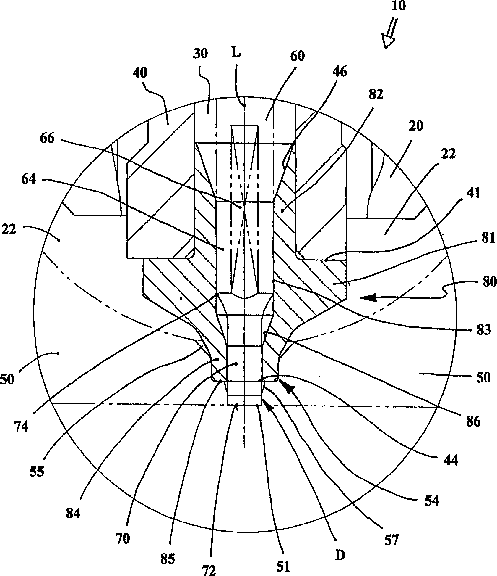
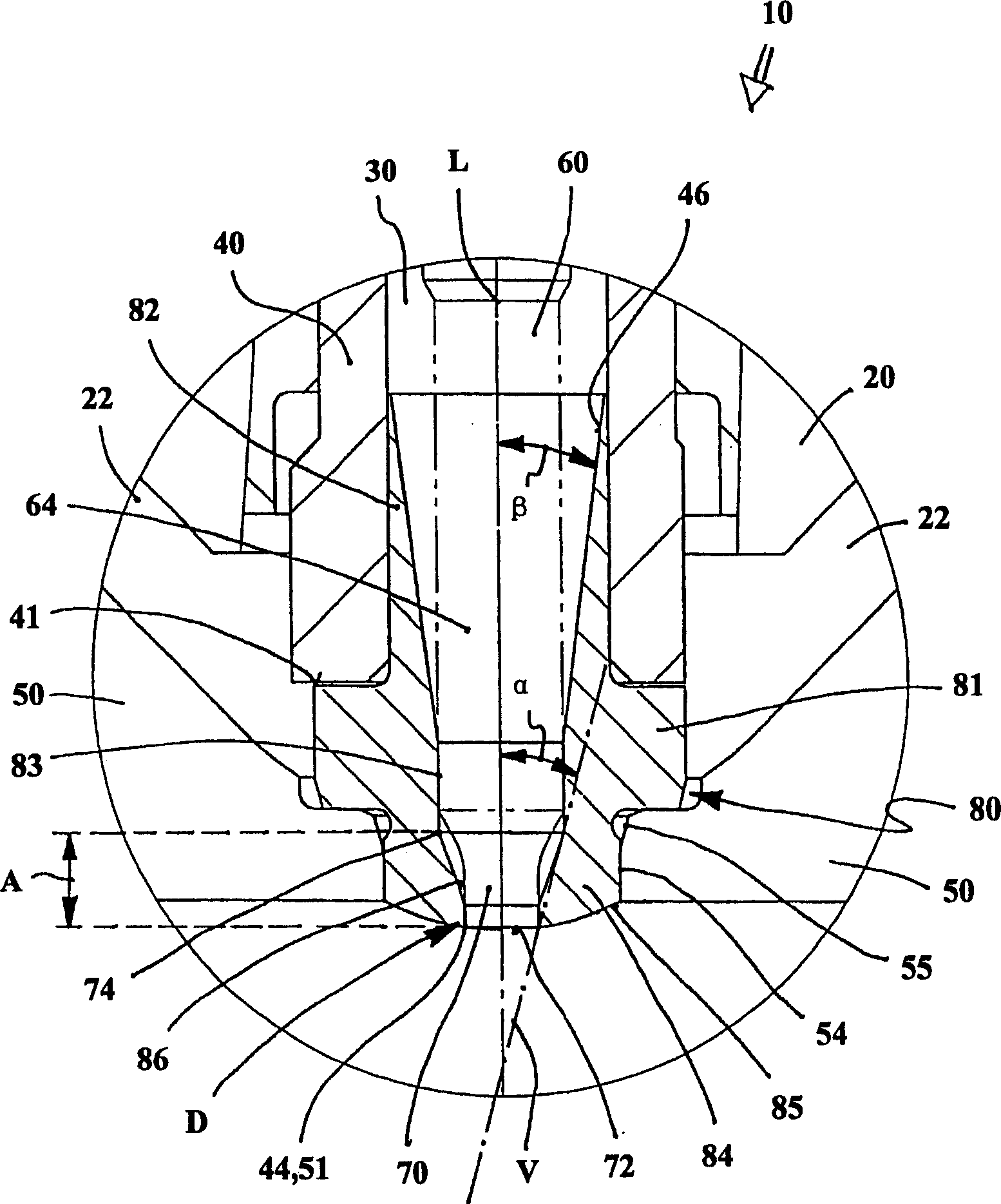
[0024] figure 1 The needle valve orifice designated as a whole by 10 is a component part of the (not shown) die-casting tool. It has a preferably externally heated nozzle body 20 , in which a (not visible) material tube is formed, which delimits a melt channel 30 concentrically to the longitudinal axis L of the needle valve nozzle 10 . A nozzle mouthpiece 40 of a highly thermally conductive material is preferably screwed from below into the nozzle body 20 , and the melt channel 30 extends cylindrically downwards without a change in cross-section.

[0025] The melt to be processed, eg metal, silicon or plastic melt, is conveyed via the melt channel 30 into a mold cavity (not shown in detail). The cavity is formed between at least two mold parts 50 which are fastened to the formwork (not shown) and delimit a riser 51 concentrically to the longitudinal axis L of the heating channel nozzle 10 .

[0026] Between the nozzle mouth piece 40 and the mold part 50, a centering body 80 ...


PUM


Abstract

The invention relates to a needle valve nozzle (10) for an injection mould, comprising a nozzle body (20) that contains at least one melt channel (30), the latter terminating against or in a nozzle mouthpiece (40) and having a fluidic connection to a mould cavity of the injection mould that is formed by at least one mould insert (50). A shut-off needle (60) penetrates the melt channel (30) and the nozzle mouthpiece (40) and can be displaced longitudinally through said parts, moving from an open position into a closed position. At least one infeed cone (46) is provided upstream of a seal seat (D), in order to centre the shut-off needle (60), the lower end of which forms a shut-off part (70). The aim of the invention is to guarantee a constantly precise guidance and sealing of the needle, whilst at the same time preventing an impairment of the temperature distribution in the vicinity of the nozzle tip. To achieve this, the nozzle mouthpiece (40) consists of a material with high thermal conductivity, whilst the or each infeed cone (46) for the shut-off needle (60) is configured in a centring body (80) consisting of wear-resistant material and running concentrically with the longitudinal axis (L) of the needle valve nozzle (10). The centring body is held against and / or in the nozzle mouthpiece (40) in a positive-fit and its end section (84), which forms an outlet opening (44) for the melt, can be engaged with the mould insert (50).

Description

technical field [0001] The invention relates to a needle valve for an injection molding tool according to the preamble of claim 1 . Background technique [0002] Needle valves are used in die-casting molds to convey a melt at a predeterminable temperature to the mold head (molding part) under high pressure. Most pneumatically or hydraulically driven shut-off needles are used to periodically open and close the melt outlet, for example when the plastic material has to be injected in sections (tandem gating system). [0003] Each shut-off needle is mounted axially displaceably in the mold-side region of the needle valve orifice and passes centrally through the melt channel in the nozzle-side region (see eg DE 32 49 486 C3 or DE 3403 603 A1). The melt channel usually ends in the nozzle mouthpiece, the end side of which forms the outlet for the melt. In the closed position, the lower end of the mostly cylindrical closing needle engages in a likewise cylindrical sealing seat for...

Claims


Application Information

Patent Timeline
Patent Type & Authority Applications(China)
IPC IPC(8): B29C45/28B29C45/27
CPCB29C45/2806B29C2045/2858B29C2045/2879B29C45/28B29C45/27
Inventor 赫贝尔·京特
Owner GUNTHER GMBH & CO METALLVERARBEITUNG
Learn More