
Full optical fibre circular phase converter and its processing method

A processing method and all-fiber technology, applied in instruments, optics, nonlinear optics, etc., can solve the problems of small second-order nonlinearity, impossible, and difficult to realize optical fiber, and achieve small scattering and loss, simple processing, and low cost. Effect

Inactive Publication Date: 2006-01-25
PEKING UNIV
View PDF0 Cites 3 Cited by
  • Summary
  • Abstract
  • Description
  • Claims
  • Application Information

AI Technical Summary

Problems solved by technology

However, the obtained second-order nonlinearity is very small, and the required π radian phase modulation is usually not achieved at a distance of about 10 cm, and it is very difficult or even impossible to make a longer section of optical fiber.

Method used


Image

  • Full optical fibre circular phase converter and its processing method
  • Full optical fibre circular phase converter and its processing method
  • Full optical fibre circular phase converter and its processing method

Examples


Embodiment Construction

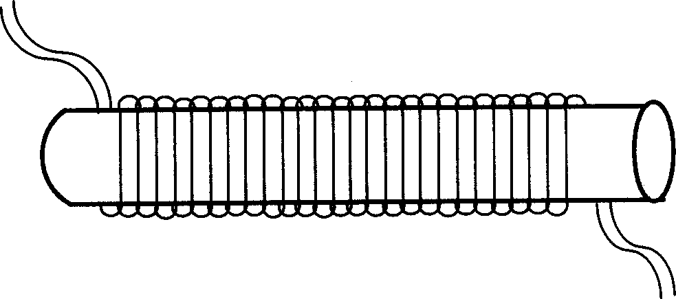
[0025] Such as figure 1 As shown, the present invention first coats the electrode on the outer surface of the insulating cylindrical rod, coats the epoxy resin on the outer surface of the electrode rod, and directly winds the optical fiber on the electrode rod, corrodes the outer cladding of the optical fiber, and then coats the outer surface of the optical fiber Electrodes are plated on the surface, and high voltage and high temperature are applied between the two electrodes to polarize the optical fiber.

[0026] The processing procedure of the present invention is divided into two major steps, and the first step is to make the optical fiber ring, plate the electrode, specifically as follows:

[0027] 1) Choose a cylindrical rod of insulating material with a length of 3-4cm and a diameter of 2-3cm, preferably ceramic. The surface of the cylindrical rod is ground and polished, and then evenly plated with a layer of electrodes (internal electrodes) to form an electrode rod, a...


PUM


Abstract

The invention is a full optical fiber coiled phase regulator, including an electrode rod, and a peeled optical fiber, where the optical fiber is pasted firmly with the electrode plate through epoxy resin, the outer coating of the optical fiber is eroded so as to make the distance between the outer coating and the optical fiber core small enough and a layer of electrode is plated on the surface of the optical fiber, and the optical fiber is polarized by applying high temperature between the electrode on the optical fiber and that on the electrode rod. The invention is full-optical fiber so as to be easy to connect with other optical fiber and the reflection, dispersion and losses at the connection part, which has a great significance for optical fiber top. In addition, the invention is made by coiling-process, therefore, the optical fiber can be very long and meet the requirement for 0-phi phase modulation and can compensate the shortage. The invention is simple to manufacture, low-cost and can be batch-produced.

Description

technical field [0001] The invention relates to an all-fiber ring phase modulator and a processing method thereof. Background technique [0002] At present, optical phase modulators generally have LiNbO 3 Crystal phase modulators and piezoelectric ceramic phase modulators. LiNbO 3 The electro-optic coefficient of the crystal is very large, but its coupling loss with the optical fiber is also large, and there are certain backscattering and back reflections in the coupling process, which limits its application in some special occasions. For the piezoelectric ceramic phase modulator, although the coupling loss and backscattering and back reflection generated during coupling are relatively small, its bandwidth is very narrow and cannot be driven by DC voltage. Therefore, there is currently no all-fiber phase modulator driven by DC or low-frequency voltage with excellent linearity and bandwidth, which greatly limits the realization and application of all-fiber interferometric ...

Claims


Application Information

Patent Timeline
Patent Type & Authority Applications(China)
IPC IPC(8): G02F1/01G02F1/03G02F1/035
Inventor 伍刚王子宇
Owner PEKING UNIV
Learn More