Droplet deposition apparatus

A droplet and actuator technology, applied in printing, inking devices, etc., can solve problems such as uneven shrinkage and crossing of piezoelectric materials

Inactive Publication Date: 2006-01-18
XAAR TECH LTD
View PDF3 Cites 2 Cited by
  • Summary
  • Abstract
  • Description
  • Claims
  • Application Information

AI Technical Summary

Problems solved by technology

This shrinkage is not uniform across the piezoelectric material, and this re

Method used


Image

  • Droplet deposition apparatus
  • Droplet deposition apparatus
  • Droplet deposition apparatus

Examples


Embodiment Construction

[0061] In the drawings, similar elements are denoted by the same reference numerals.

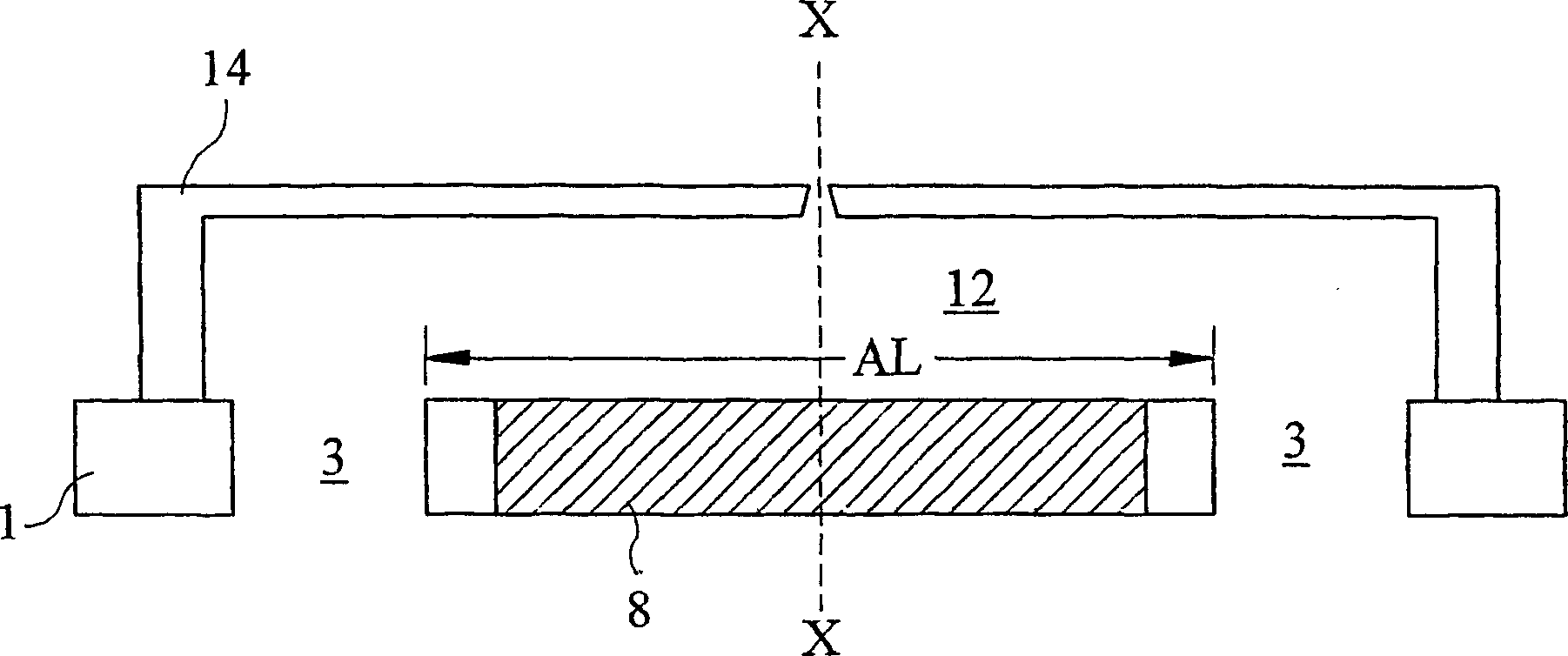
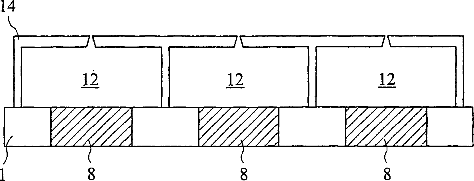
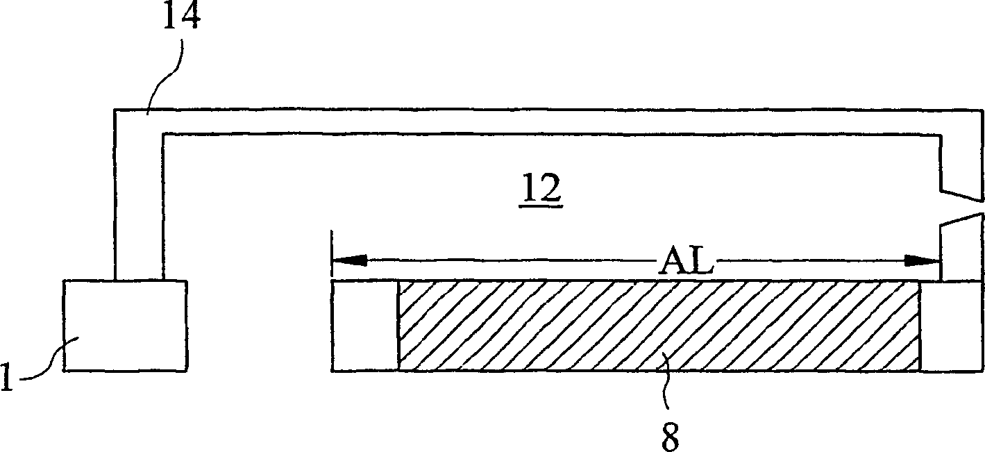
[0062] refer to Figure 1A with 1B ,in Figure 1B is along Figure 1A In the cross-sectional view of line X-X, the impulse droplet printing head consists of a cover element 14 and an actuator element 1, and has an ejection chamber 12 defined between these elements.

[0063] The cover element 14 is made of a nickel alloy, which is a material thermally matched to the material of the actuator element 12 , which is mainly silicon but also includes the active part 8 . The firing chamber is elongate and has an acoustic length AL defined by the distance between ink supply ports 3 formed through the actuator elements. The variation in ink depth at the ink supply port provides an acoustic boundary that effectively reflects sound waves propagating in the ink.

[0064] The ink supply port 3 is arranged to supply ink into the chamber or to allow a jetting fluid to circulate through the chamber by pas...


PUM


Abstract

A drop on demand ink jet printer, has a passive component (14) defining ink ejector chambers (12) with respective ejection nozzles (16); and an actuator component comprising a body (2) with an opening and an actuator structure (8) located within the opening. The actuator structure is formed of piezoelectric material by moulding from a slurry or vacuum forming of flexible sheets using formers that are burnt away. MEM's techniques may also be employed to build the structure on a silicon wafer using a succession of masked deposition; etch back and similar process steps.

Description

technical field [0001] The present invention relates to a drop deposition apparatus and, in particular, to drop-on-demand inkjet printers, components thereof and methods of their manufacture. Background technique [0002] Drop-on-demand inkjet printers typically fall into two broad categories: bubble jet or mechanical. Bubble jet printers eject droplets by selectively heating a fluid and generating air bubbles that provide sufficient force to eject the droplets. Mechanical printers eject droplets by changing the volume of the chamber to apply pressure to the fluid within the chamber and thereby eject the droplets. The present invention relates generally to mechanical drop-on-demand inkjet printers and more particularly to mechanical printers using piezoelectric materials. Therefore, the bubble jet device will not be described in more detail. [0003] The piezoelectric material traditionally used in inkjet printing is lead zirconate titanate (PZT) ceramic material. PZT is...

Claims


Application Information

Patent Timeline
IPC IPC(8): B41J2/14
CPCB41J2/14209B41J2002/14225B41J2202/20B41J2/14201B41J2/045B41J2/14
Inventor 斯蒂芬·坦普尔罗伯特·哈维罗伯特·乔纳森·洛保罗·雷蒙德·德鲁里
Owner XAAR TECH LTD
Why Eureka
Try Eureka