Biwheel braking device and light triwheel or tetrawheel cycle using said device
A brake device and a technology for four-wheeled vehicles, which are applied to motor vehicles, bicycles, bicycle accessories, etc., can solve the problems of increased vehicle weight and processing costs, uneven force on both sides of the brake, and difficulty in manpower driving, etc., to achieve complete vehicle Small and light, outstanding functions, and simple frame structure
- Summary
- Abstract
- Description
- Claims
- Application Information
AI Technical Summary
Problems solved by technology
Method used
Image
Examples
Embodiment 1
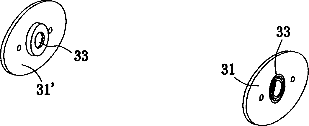
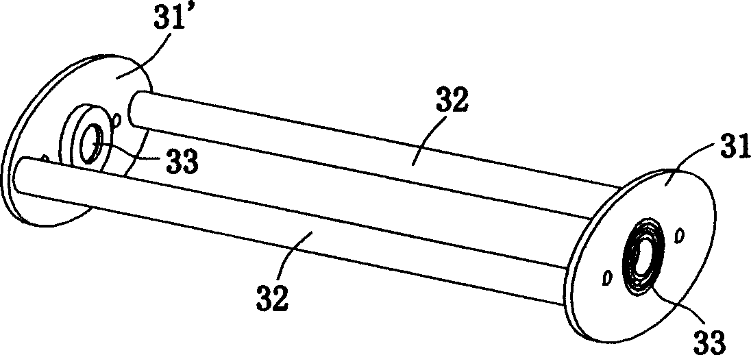
[0048] Embodiment one: the present embodiment is a portable tricycle that adopts double rear wheel brakes. As shown in Figure 5, the main frame 1 of this tricycle adopts the ordinary bicycle frame, and its flat fork 41 and vertical fork 44 also adopt the flat fork and vertical fork of ordinary bicycles (because the opening of the left and right fork pipes is small, it is called It is a small flat fork and a small vertical fork), and the difference is that the joints on both sides of the rear end of the flat fork 41 are improved. The improved flat fork joints 42 and 42 are semi-elliptical sheets (rectangular sheets are also acceptable), made of metal plates with a thickness of 3mm, and are provided with 3 assembly grooves opening downwards, wherein the assembly grooves on both sides The groove is used to install the two transverse connecting pipes 32, 32 described below, and the assembly groove in the middle is clearance fit with the rear axle 9, so that the rear axle 9 can run...
Embodiment 2
[0052] Embodiment two: as shown in Figure 8, the present embodiment is a portable four-wheel vehicle that adopts double rear wheel brakes. The brake 2 in the braking device adopts a common bicycle brake, and the composition of the brake 2 and the connecting piece assembly 3 and its connection method, and the connection method between the brake 2 and the connecting piece assembly 3 are the same as those in the embodiment. The link assembly 3 is installed on the rear portion of the main frame 1 through the positioning connector 4. The positioning connector 4 includes a guide plate 45 and shock absorbers 46, 46. The front end of the guide plate 45 is hinged with the main frame 1, and its rear end It is fixedly connected with the transverse connecting pipes 32, 32 in the connecting plate assembly 3, and elastically connected with the main frame 1 through shock absorbers 46, 46.
[0053] The brake box 23,23', the brake disc 25,25', the connecting rod 27, and the middle joint 28 in ...
PUM
 Abstract
Description
Claims
Application Information
 - R&D
- Intellectual Property
- Life Sciences
- Materials
- Tech Scout
- Unparalleled Data Quality
- Higher Quality Content
- 60% Fewer Hallucinations
Browse by: Latest US Patents, China's latest patents, Technical Efficacy Thesaurus, Application Domain, Technology Topic, Popular Technical Reports.
© 2025 PatSnap. All rights reserved.Legal|Privacy policy|Modern Slavery Act Transparency Statement|Sitemap|About US| Contact US: help@patsnap.com


