
Photoelectric mixed exchanging struture supporting light burst/group exchanging

A packet switching, optoelectronic hybrid technology, applied in electrical components, wavelength division multiplexing systems, electromagnetic wave transmission systems, etc., can solve the problems of optical power loss, high loss rate, complex series design and depth design, etc., and achieve good performance. , the effect of reducing the loss rate and reducing the delay

Inactive Publication Date: 2006-01-04
UNIV OF ELECTRONICS SCI & TECH OF CHINA
View PDF0 Cites 19 Cited by
  • Summary
  • Abstract
  • Description
  • Claims
  • Application Information

AI Technical Summary

Problems solved by technology

Compared with packet switching in the electrical domain, its loss rate is too high
[0018] 2) FDL cannot provide random access, but can only provide fixed delay, the equipment is bulky and has optical power loss
Moreover, its series design and depth design are more complicated, and there are many factors to be considered
Data caching and limited ability to resolve conflicts

Method used

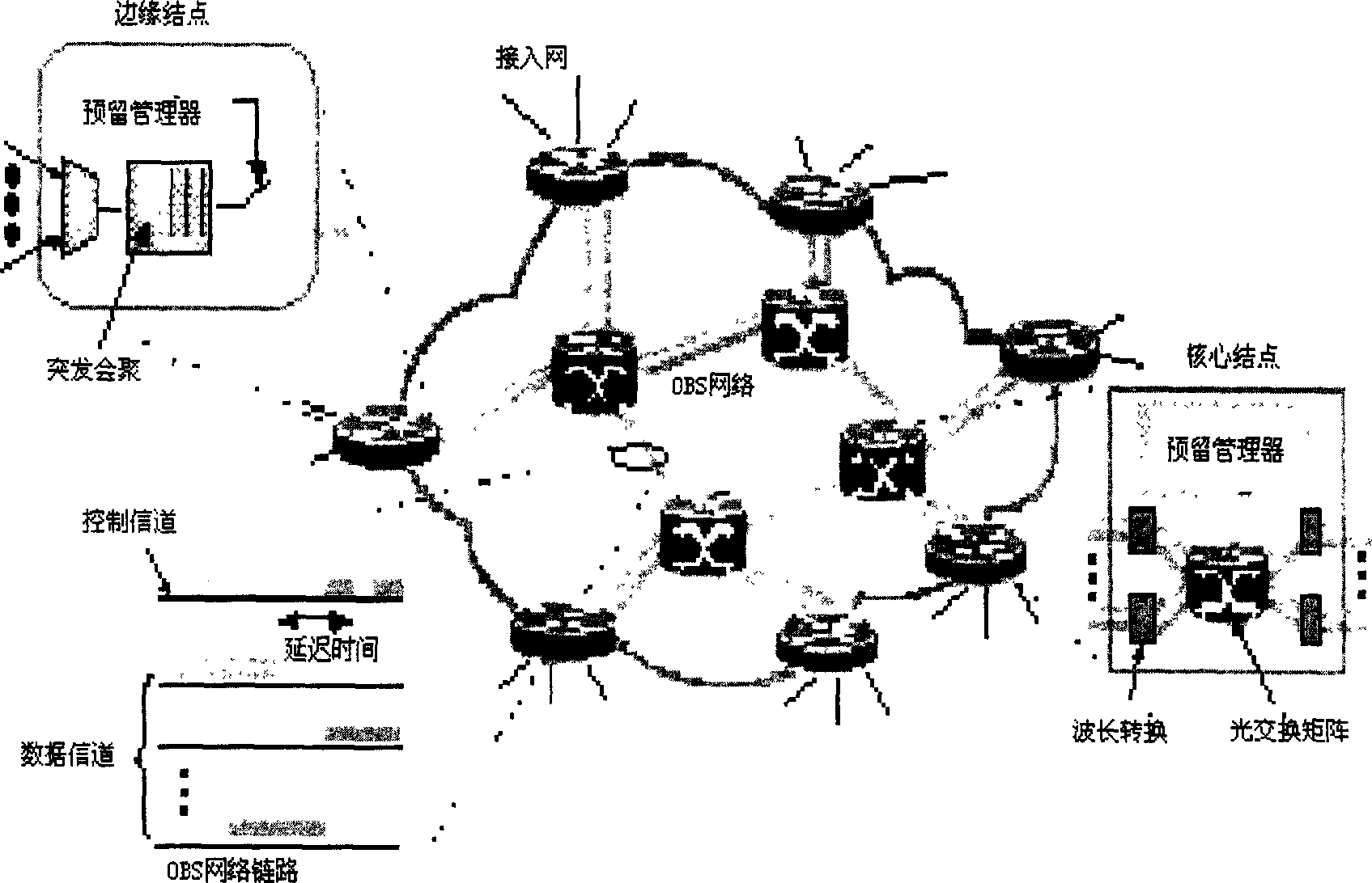
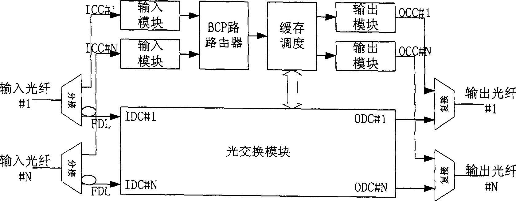
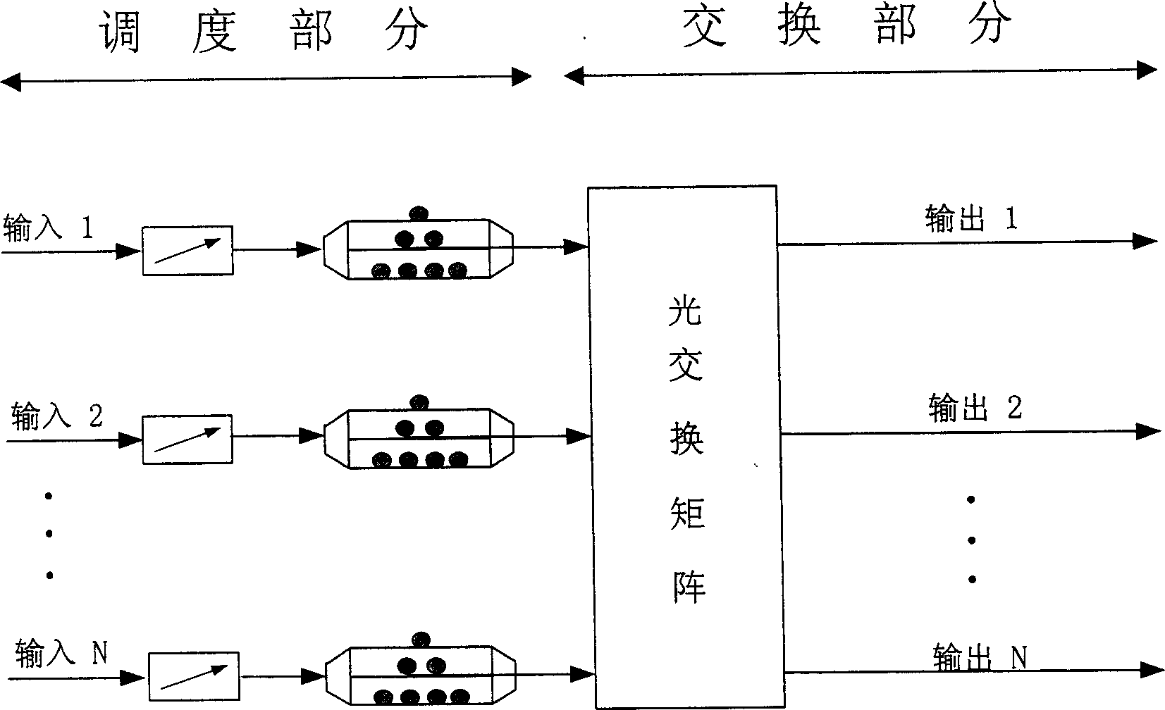

Image

  • Photoelectric mixed exchanging struture supporting light burst/group exchanging
  • Photoelectric mixed exchanging struture supporting light burst/group exchanging
  • Photoelectric mixed exchanging struture supporting light burst/group exchanging

Examples


Embodiment 1

[0064] Embodiment 1, 100% no packet loss embodiment after conflict

[0065] See attached Figure 8 , we use a 32×32 non-internal blocking optical switch matrix; the input end has two input ports with 8 wavelength channels each, and a total of 16 input wavelength channels are used as signal input; the output end also has two output ports with 8 wavelength channels each channel, a total of 16 output wavelength channels are used as the output of the signal. The difference from the input end is that the 16 wavelength converters can adjust the output signal to the required wavelength; the remaining 16 wavelength channels at the input end and the output end and 16 A photoelectric converter, 16 RAM caches, and 16 electro-optic converters are combined to form the electrical cache part to provide 16 electrical cache channels to resolve conflicts.

[0066] When the node starts to work, there is no data stored in the electrical cache, and all data is input from 16 input wavelength chann...

Embodiment 2

[0067] Embodiment 2. An embodiment in which there is a certain loss rate after the conflict

[0068] In practical applications, if a certain degree of data loss rate is allowed, then the attached Figure 9 The configuration can also achieve better cost performance. As shown in the figure, a 32×32 non-blocking optical switch matrix is ​​still used; the input end has three input ports with 8 wavelength channels each, and a total of 24 input wavelength channels are used as signal input; the output end has three output ports with 8 wavelength channels each channels, a total of 24 output wavelength channels are used as signal output, and 24 wavelength converters can adjust the output signal to the required wavelength; the remaining 8 wavelength channels and 8 photoelectric converters at the input and output ends, 8 A RAM cache and 8 electrical-optical converters are combined to form the electrical cache part to provide 8 electrical cache channels to resolve conflicts. The additio...


PUM


Abstract

This invention provides a photoelectric mixed exchange structure supporting light burst / packet exchange, which takes optical exchange as the main thing and applies a buffer storage channel composed of a photoelectric converter, RAM buffer storage and an electro optical converter connected by electric field, takes electric-field buffer storage to replace light buffer storage (FDL) and adds with suitable electric-field exchange. This invention utilizes electric-field buffer storage to solve conflict effectively, which is the main reason for loosing data in optical network.

Description

technical field [0001] The invention belongs to the technical field of switching control in communication systems, and particularly relates to the switching structure of core nodes in optical burst / packet switching networks. Background technique [0002] With the scale of the Internet and the exponential growth of Internet services, people's demand for network bandwidth is also increasing sharply, so the requirements for the transmission capacity of the network and the processing capacity of routers and switches are also increasing. Dense Wavelength Division Multiplexing (WDM for short) can multiplex multiple wavelength channels on one optical fiber, greatly improving the transmission capacity of a single optical fiber. Utilizing it can establish a broadband basic network to meet the growth of Internet services, and better solve the problem of network transmission. The current technology can multiplex 80-120 wavelengths on one optical fiber, with a total transmission capaci...

Claims


Application Information

Patent Timeline
IPC IPC(8): H04Q11/00H04J14/02H04B10/12
Inventor 谭伟王晟周韬许都
Owner UNIV OF ELECTRONICS SCI & TECH OF CHINA
Learn More