High-temperature superconductive and permanent magnet microgyrorotor with stabilized hung

A permanent magnet rotor and high-temperature superconducting technology, applied to rotating gyroscopes, etc., can solve problems such as limited application range, difficulty in assembly and debugging, and difficulty in cost reduction, and achieve the effects of expanding application range, low power consumption, and good cooling effect

Inactive Publication Date: 2005-12-28
SHANGHAI JIAO TONG UNIV
View PDF1 Cites 7 Cited by
  • Summary
  • Abstract
  • Description
  • Claims
  • Application Information

AI Technical Summary

Problems solved by technology

The overall structure of the gyroscope adopts the traditional double-frame structure, and only the bearing support adopts a superconducting structure. The gyroscope with this overall structure is large in size, complex in structure, and difficult to assemble and debug. It is difficult to reduce its size by using micro-machining technology. Small, and to achieve mass production, cost reduction is difficult
This greatly limits its application range, especially in micro-satellites, micro-aircraft and other applications requiring small gyroscopes.

Method used


Image

  • High-temperature superconductive and permanent magnet microgyrorotor with stabilized hung
  • High-temperature superconductive and permanent magnet microgyrorotor with stabilized hung
  • High-temperature superconductive and permanent magnet microgyrorotor with stabilized hung

Examples


Embodiment Construction

[0021] Such as figure 1 As shown, the present invention comprises: liquid nitrogen Dewar 1, gyro rotor 32, gyro upper stator 33, gyro lower stator 34, liquid nitrogen Dewar cover 7, liquid nitrogen 8, gyro upper casing 9, gyro lower casing 16, Gyro support column 17. The connection method is as follows: the liquid nitrogen Dewar cover 7 is set on the liquid nitrogen Dewar 1 , and the liquid nitrogen 8 is set in the cavity surrounded by the liquid nitrogen Dewar cover 7 and the liquid nitrogen Dewar 1 . The gyro lower casing 16 is set on the liquid nitrogen Dewar 1 through the gyro support column 17 .

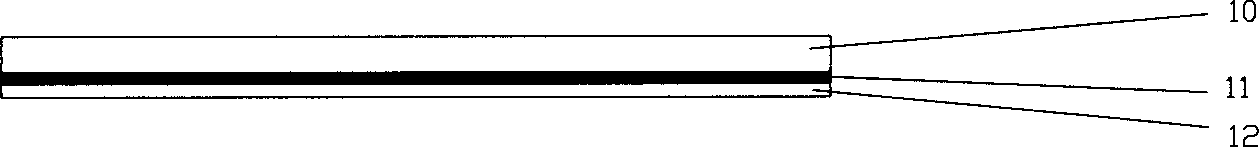
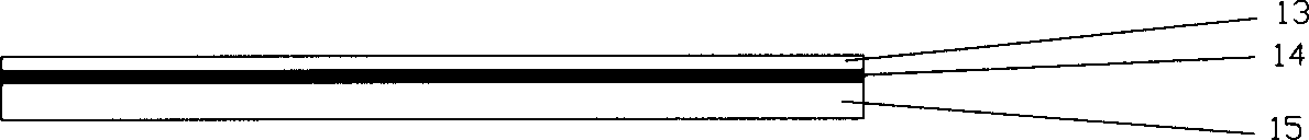
[0022] Such as Figure 4 As shown, the gyro rotor 32 is composed of a rotor driving and detecting moment adding layer 2, a cylindrical silicon nitride insulating material 3, a cylindrical permanent magnet material 4, a cylindrical silicon nitride insulating material 5, and a rotor driving and detecting moment adding layer 6. The cylindrical silicon nitride The insulating mate...


PUM


Abstract

A micro-gyroscope of permanent magnet rotor stably suspended by high temperature superconductor is prepared by setting gyroscope bottom shell on piqued nitrogen Dewar through support column; forming top and bottom stators of gyroscope by high temperature superconductor, silicon nitride insulation material and stator driving detection moment layer; forming gyroscope rotor by two layers of rotor driving detection moment layer, two layers of cylindrical silicon nitride insulation material and cylindrical permanent magnet material .

Description

technical field [0001] The invention relates to a device in the technical field of micro-electromechanical systems, in particular to a micro-gyroscope with a high-temperature superconducting stabilized suspension permanent magnet rotor. Background technique [0002] The suspended rotor micro-gyroscope does not require mechanical support, and integrates the high precision of traditional gyroscopes with the characteristics of small size and low cost of micro-mechanical technology. Non-contact suspension support is an important guarantee for the work of suspended rotor micro-gyroscopes. At present, suspended rotor micro-gyroscopes mainly use electromagnetic and electrostatic forces to achieve suspension support. [0003] After searching the literature of the prior art, it was found that the Japanese patent JP1193612 describes a micro-gyroscope made of superconductors. The core structural feature of the gyroscope is that the rotor is attached to two superconductors, and the two ...

Claims


Application Information

Patent Timeline
IPC IPC(8): G01C19/16
Inventor 张卫平陈文元段永瑞
Owner SHANGHAI JIAO TONG UNIV
Why Eureka
Try Eureka