
Apparatus for testing reactance parameter of permanent magnet motor based on small DC attenuation

A technology of permanent magnet motor and decay method, which is applied in the direction of motor generator testing, etc., can solve the problems of lack of good connection between motor running states, lack of saturation parameter values, and failure to consider repeatability and accuracy.

Inactive Publication Date: 2005-12-21
SHENYANG POLYTECHNIC UNIV
View PDF0 Cites 9 Cited by
  • Summary
  • Abstract
  • Description
  • Claims
  • Application Information

AI Technical Summary

Problems solved by technology

[0002] The conventional DC attenuation method is to use the transition process in which the stable DC current in the armature winding decays to zero due to the loss of the excitation voltage to determine the reactance parameters of the permanent magnet motor; during the transition process, the degree of saturation of the motor is constantly changing. In this way, the correct saturation parameter value cannot be obtained by processing the DC attenuation curve
At the same time, due to the cross-saturation phenomenon of permanent magnet motors, the conventional DC attenuation method does not take this into account, and it is not well connected with the actual operating state of the motor
Moreover, the use of this method to measure the reactance parameters of permanent magnet motors is usually limited to the basis of using limited components in the laboratory, without considering repeatability and accuracy, and there are no reports on test instruments specially used in actual engineering

Method used


Image

  • Apparatus for testing reactance parameter of permanent magnet motor based on small DC attenuation
  • Apparatus for testing reactance parameter of permanent magnet motor based on small DC attenuation
  • Apparatus for testing reactance parameter of permanent magnet motor based on small DC attenuation

Examples


Embodiment Construction

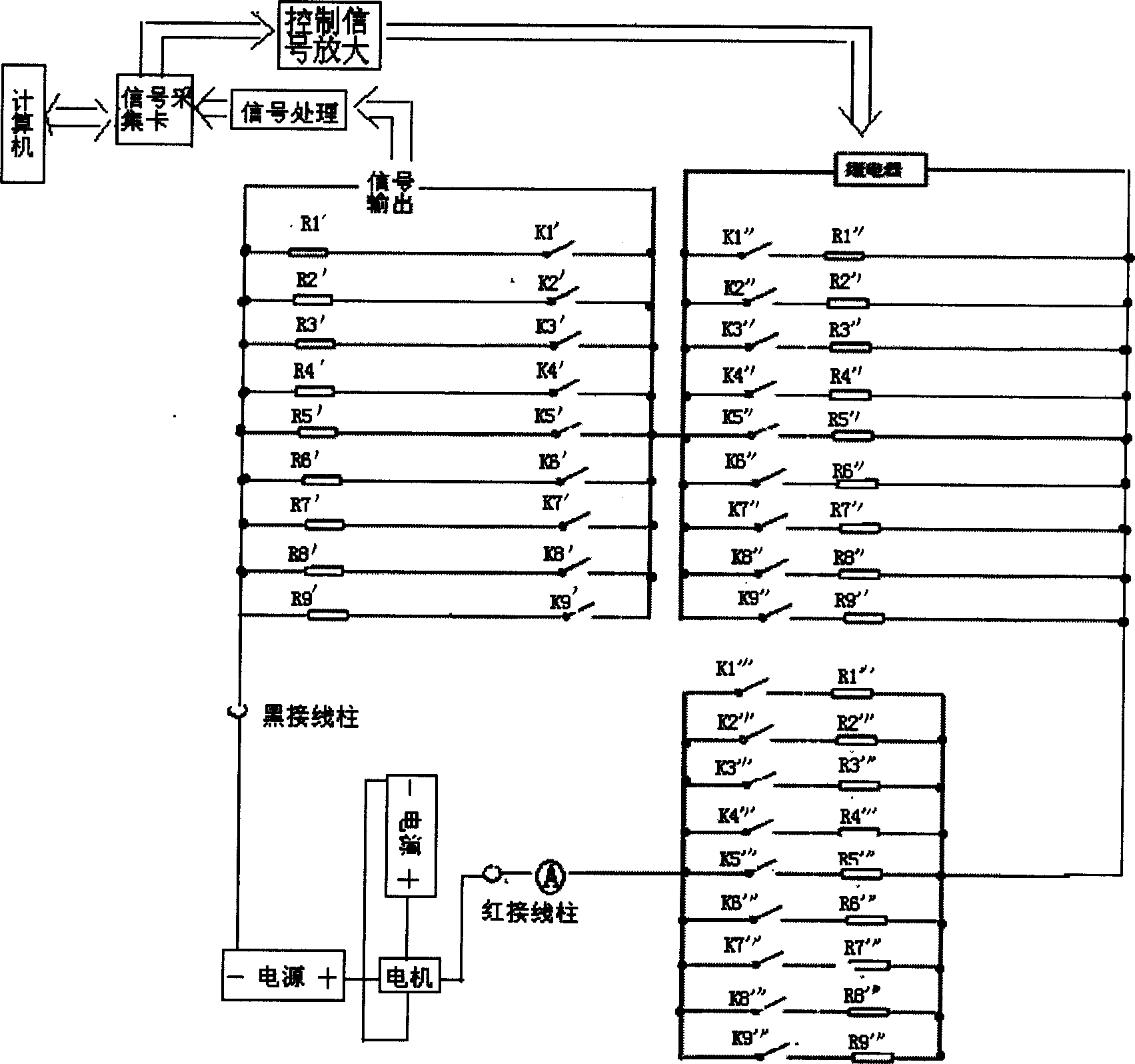
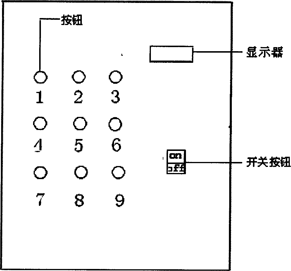
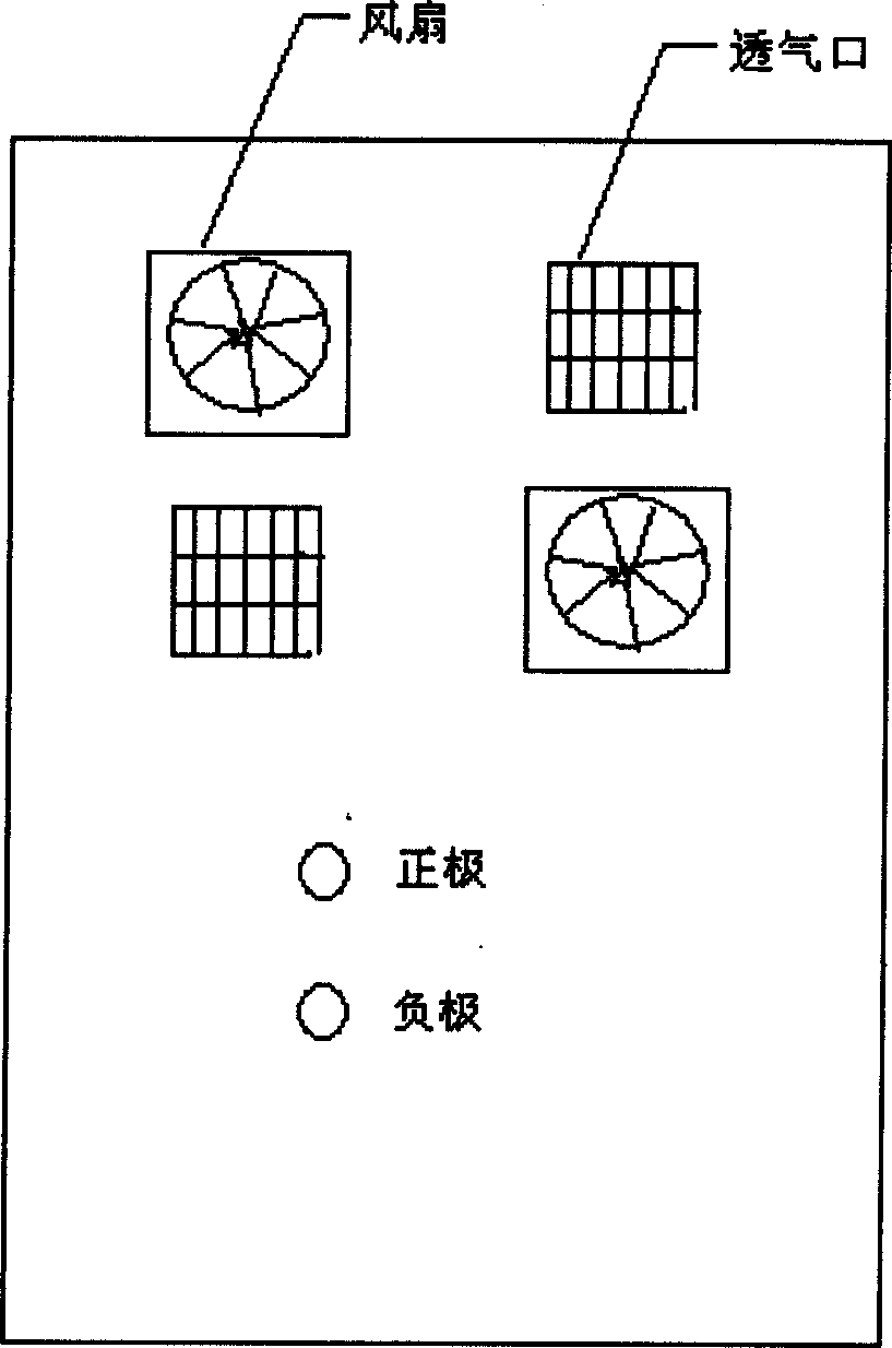
[0070] Combine below Figure 1 to Figure 14 Embodiments of the present invention will be described in detail. The device for realizing the test includes a DC power supply, a transformer, a rectification module, a data acquisition card, a signal processing and protection module, a computer control signal amplification module, a computer, a relay, and a non-inductive resistor.

[0071] To meet the test requirements of various rare earth permanent magnet synchronous motors, the test range of the instrument should be wide. Based on various types of rare earth permanent magnet synchronous motors on the market, the test range of 0.05A~40A has basically met the test requirements of various signals. Rare earth permanent magnet synchronous motors determine the direct axis and quadrature axis in the state of magnetic circuit saturation in its windings. The steady-state and transient reactance values ​​of current requirements. In order to ensure that the saturation degree of the magnet...


PUM


Abstract

The device includes DC power supply, transformer, rectification module, data acquisition card, single process and protection module, signal amplification module, computer, relay, non-inductive resistance etc.. Including two pieces of triodes, the control signal amplification module magnifies a control signal sent from the computer by the said amplifying circuit in order to realize function of attenuating DC through controlling on / off of the relay. The single process and protection module includes operational amplification circuit (OAC), control switch, regulation tube. Being obtained from input signal of passing through OAC, the amplified voltage signal subtracts difference mode signal obtained by two control switches, then is amplified in operational amplifier. Amplified attenuation signal is sent to the data acquisition card which transfers collected signal to computer for carrying out calculating parameter of reactance.

Description

technical field [0001] The invention belongs to a motor reactance parameter testing device, in particular to a device for testing the reactance parameter of a permanent magnet motor based on a small direct current attenuation method. Background technique [0002] The conventional DC attenuation method is to determine the reactance parameters of the permanent magnet motor by using the transition process in which the stable DC current in the armature winding decays to zero due to the loss of the excitation voltage; during the transition process, the saturation degree of the motor is constantly changing. In this way, the correct saturation parameter value cannot be obtained by processing the DC attenuation curve. At the same time, due to the cross-saturation phenomenon of permanent magnet motors, the conventional DC attenuation method does not take this into account, and is not well connected with the actual operating state of the motor. Moreover, the use of this method to mea...

Claims


Application Information

Patent Timeline
Patent Type & Authority Applications(China)
IPC IPC(8): G01R31/34
Inventor 唐任远安忠良王世伟王惠军
Owner SHENYANG POLYTECHNIC UNIV
Learn More