Signal generator
A signal generation and signal technology, applied in multiplexing communication, modulated carrier system, transmission system, etc., can solve the problems of widening signal frequency band, large power consumption, and increased data errors, so as to suppress the peak value and increase power consumption , The effect of suppressing the peak voltage
- Summary
- Abstract
- Description
- Claims
- Application Information
AI Technical Summary
Problems solved by technology
Method used
Image
Examples
no. 1 Embodiment approach
[0063] Next, a first embodiment of the present invention will be described.
[0064] Figure 4 It is a configuration diagram showing the first OFDM transmission device 10 of the present invention.
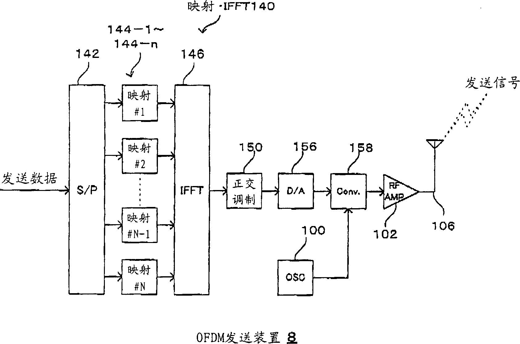
[0065] Such as Figure 4 As shown, the first OFDM transmitting device 10 is composed of a mapping / IFFT unit 140, a local signal generating unit 100, RF-AMPs 102-1, 102-2, a combining unit 104, a transmitting antenna 106, a first transmitting signal generating unit 14 and a first The peak suppression unit 40 is configured.
[0066] The transmission signal generation unit 14 is composed of a quadrature modulation unit 150-1, a buffer unit 152, a subtraction unit 154, a D / A conversion unit 156-1, and a frequency conversion unit 158-1.
[0067] In addition, the peak suppression unit 40 is composed of a peak value / peak position (PV / PL) detection unit 400, a peak carrier (PC) extraction unit 410, a peak carrier generation unit 412, a quadrature modulation unit 150-2, and a D / A convers...
no. 2 Embodiment approach
[0115] Next, a second embodiment of the present invention will be described.
[0116] Figure 9 It is a diagram showing the configuration of the second OFDM transmission device 18 of the present invention.
[0117] Such as Figure 9 As shown, the second OFDM transmitting device 18 is composed of a mapping.IFFT part 140, a local signal generating part 100, RF-AMP102-1, 102-2, a combining part 104, a transmitting antenna 106, a second transmitting signal generating part 16 and a first The peak suppression unit 40 is configured.
[0118] Although the second transmission signal generation unit 16 includes the same as the first transmission signal generation unit 14 ( Figure 4 ) same structure, but there is a difference in the structure of both.
[0119] That is, in the first transmission signal generation unit 14, the quadrature modulation unit 150-1 exists between the mapping / IFFT unit 140 and the buffer unit 152, but in the second transmission signal generation unit 16, the...
no. 3 Embodiment approach
[0138] Next, a third embodiment of the present invention will be described.
[0139] Figure 11 It is a configuration diagram showing the third OFDM transmission device 20 of the present invention.
[0140] Such as Figure 11 As shown, the third OFDM sending device 20 adopts the following structure: remove Figure 4 Combining unit 104 and transmitting antenna 106 of first OFDM transmitting apparatus 10 shown in , are connected to directional transmitting antennas 110-1 and 110-2 on the respective output sides of RF-AMPs 102-1 and 102-2.
[0141] That is, the third OFDM transmitting apparatus 20 adopts a structure in which a transmission signal is sent from the directional transmission antenna 110-1, and a signal for peak suppression is sent from the directional transmission antenna 110-2, and the combining unit 104 is not used, and in the wireless communication line, the combined Send signal and signal for peak suppression.
[0142] For example, the directional transmittin...
PUM
 Abstract
Description
Claims
Application Information
 - R&D Engineer
- R&D Manager
- IP Professional
- Industry Leading Data Capabilities
- Powerful AI technology
- Patent DNA Extraction
Browse by: Latest US Patents, China's latest patents, Technical Efficacy Thesaurus, Application Domain, Technology Topic, Popular Technical Reports.
© 2024 PatSnap. All rights reserved.Legal|Privacy policy|Modern Slavery Act Transparency Statement|Sitemap|About US| Contact US: help@patsnap.com


