
Side driving rotary cultivator

A technology of rotary tiller and transmission box, applied in the field of rotary tiller, can solve the problems of unsuitable universal coupling and different output directions, etc.

Inactive Publication Date: 2005-11-30
徐文忠
View PDF0 Cites 4 Cited by
  • Summary
  • Abstract
  • Description
  • Claims
  • Application Information

AI Technical Summary

Problems solved by technology

However, due to the different installation positions and output directions of the side PTO shaft and the rear PTO shaft of the tractor, the existing side drive rotary cultivator is not suitable for transmission with a universal coupling

Method used


Image

  • Side driving rotary cultivator
  • Side driving rotary cultivator
  • Side driving rotary cultivator

Examples


Embodiment Construction

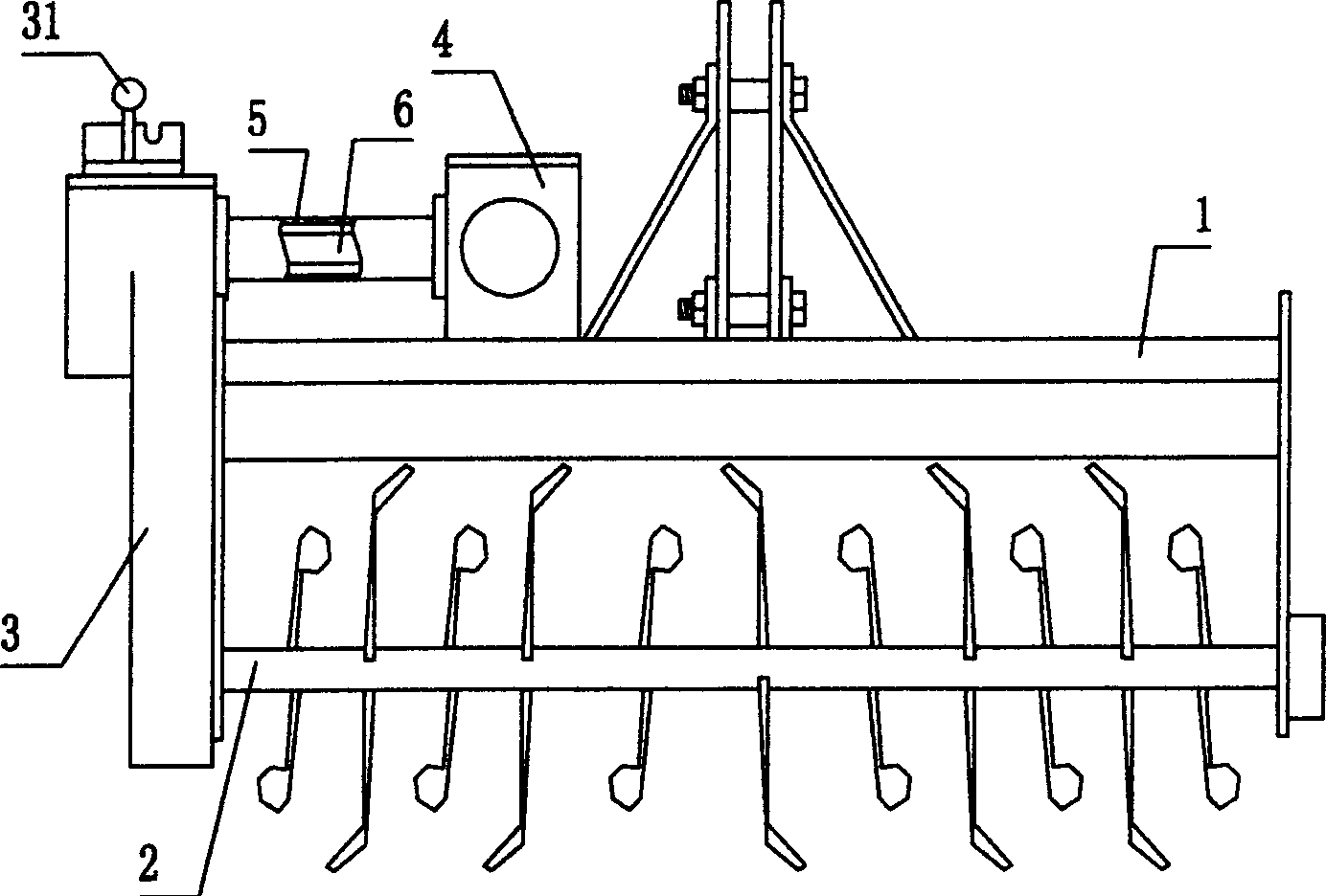
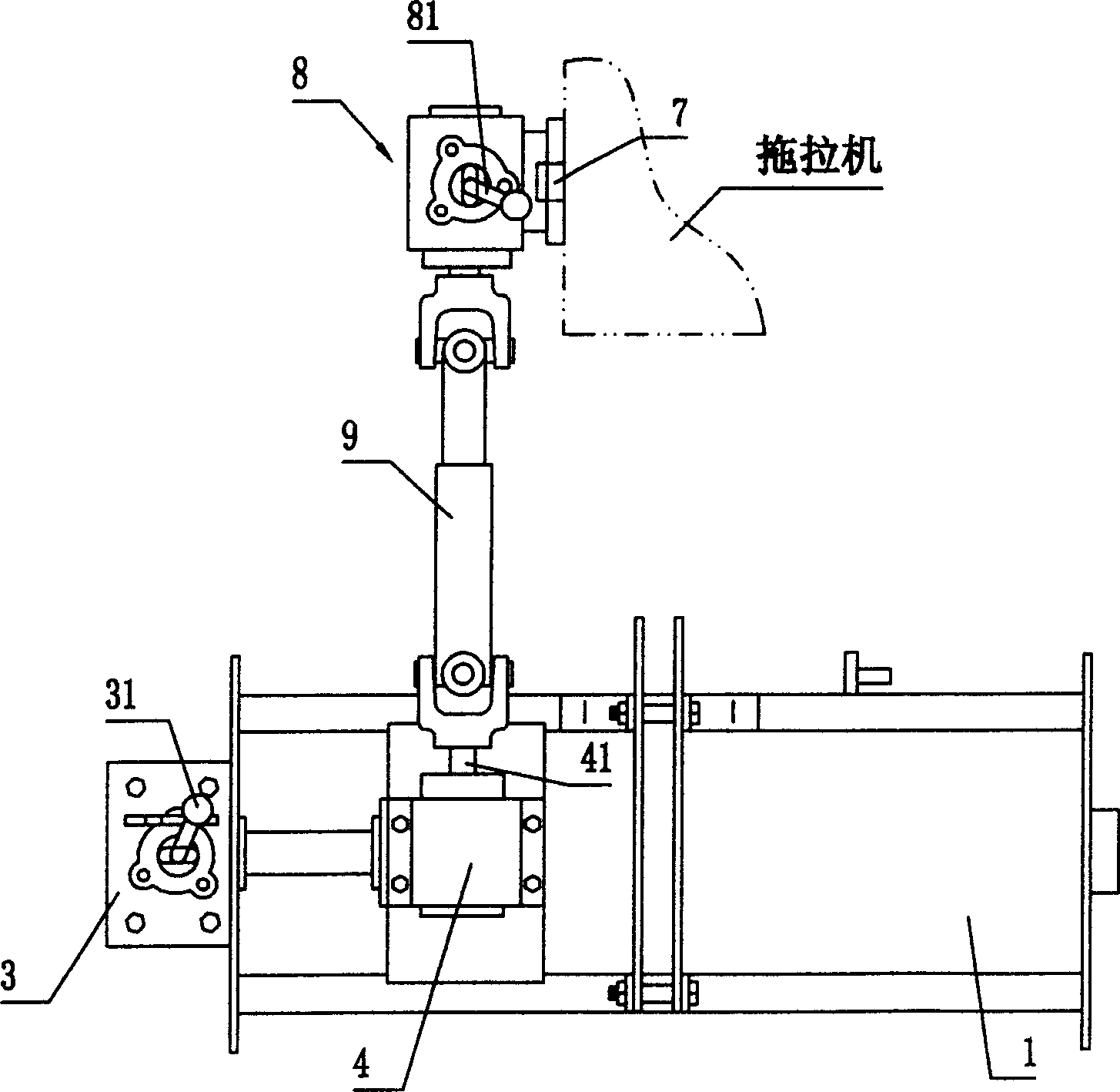
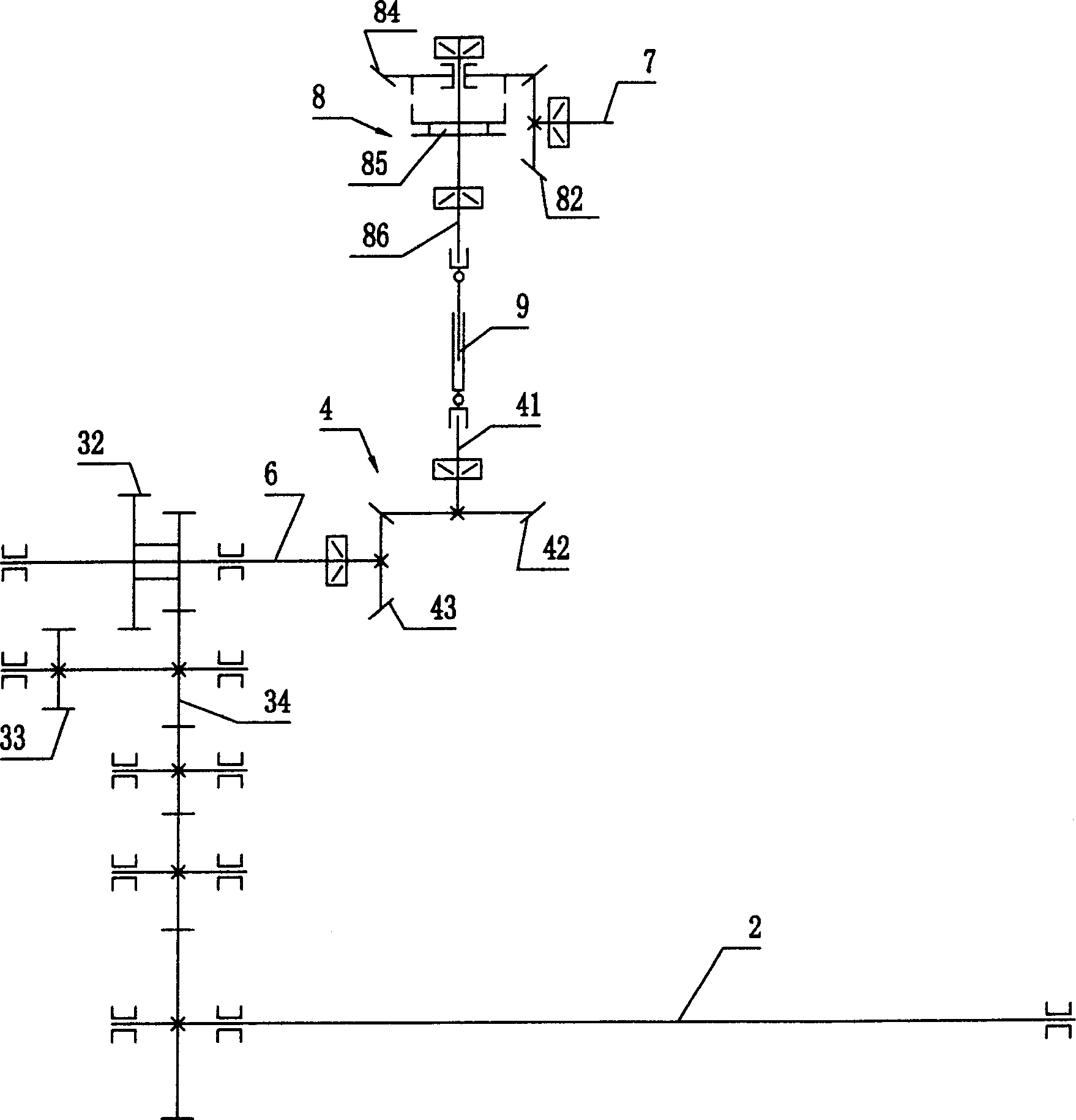
[0012] Side drive rotary tillers such as figure 1 with 2 Commonly shown, it includes a frame 1 that can be connected to the tractor by three-point suspension; the first transmission box 3 that can drive the rotary blade shaft 2 to rotate, and the first transmission box 3 is a cylindrical gearbox that can transmit power in parallel. Installed on the side of the frame 1; the second transmission box 4 is installed on the top of the frame 1, the second transmission box 4 is a bevel gear box, which can transmit power vertically, and it is offset on the side of the frame 1. Such as image 3 As shown, the second transmission box 4 includes an input shaft 41 and an output shaft, on which the third and fourth bevel gears 42 and 43 that can mesh with each other are respectively fixed, the input shaft of the first transmission box and the second transmission box The output shaft is a through shaft 6 , and a casing 5 is fixedly connected between the casing of the first transmission box ...


PUM


Abstract

The invention discloses a side driving rotary cultivator, wherein a second transmission case is arranged above the frame for conveying power vertically, and is offset to one side of the frame. The beneficial results of this improvement is that, the power of the four-wheeled tractor can be transmitted between the side power take-off shaft and the rotary cultivator through a universal coupling, the reliability of the integral job for the rotary cultivator is improved, and the rotary tillage knife shaft has two rotary tillage speeds.

Description

technical field [0001] The invention relates to the technical field of rotary tillers, in particular to a side drive rotary tiller suitable for use with a small four-wheel tractor with side power output. Background technique [0002] In the known side drive rotary cultivator, the frame is connected to the tractor by three-point suspension, the first transmission box on the side that drives the rotation of the rotary cultivator shaft is installed on one side of the frame, and the rotary cultivator shaft is supported by the first transmission box on the side. Between the box and the support plate on the other side of the frame, the power output by the tractor is received and transmitted to the first transmission box on the side. The first transmission box in the center is installed on the upper part of the frame. The advantage is that there is no missing tillage and the rotary blade Easy to sink into the soil. For small four-wheel tractors with side power output, there is oft...

Claims


Application Information

Patent Timeline
Patent Type & Authority Applications(China)
IPC IPC(8): A01B33/00
Inventor 徐文忠彭振忠彭振国王羽王忠增
Owner 徐文忠
Learn More