Hybrid drive device and automobile mounted with device
A technology of a drive device and a speed change device, which is applied to the configuration of planetary gears and speed change devices for power distribution, and the field of two electric motors, can solve the problems of mounting position and mounting direction, as well as the limitations of mounting parts.
- Summary
- Abstract
- Description
- Claims
- Application Information
AI Technical Summary
Problems solved by technology
Method used
Image

Examples
no. 1 Embodiment approach
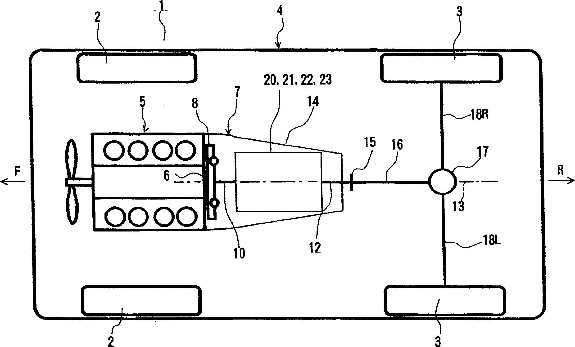
[0078] figure 1 An example of an automobile according to the present invention, that is, an automobile 1 equipped with a hybrid drive device according to the present invention is shown. The car 1 shown in the same figure is a FR (front engine, rear wheel drive) type car, and the same figure is a plan view showing its approximate structure. In addition, in an actual automobile, the arrow F direction in the figure is the front side, and the arrow R direction is the rear side.
[0079] The automobile 1 shown in the figure has a vehicle body 4 supported by left and right front wheels 2, 2 and left and right rear wheels 3, 3 as driving wheels. The internal combustion engine 5 is mounted on the front portion of the vehicle body 4 via a rubber mount (not shown), and a crankshaft 6 serving as an output shaft thereof faces in the front-rear direction. In addition, in the same figure, the output shaft formed by the rear protrusion part of a crankshaft is the crankshaft 6 shown in fig...
no. 2 Embodiment approach
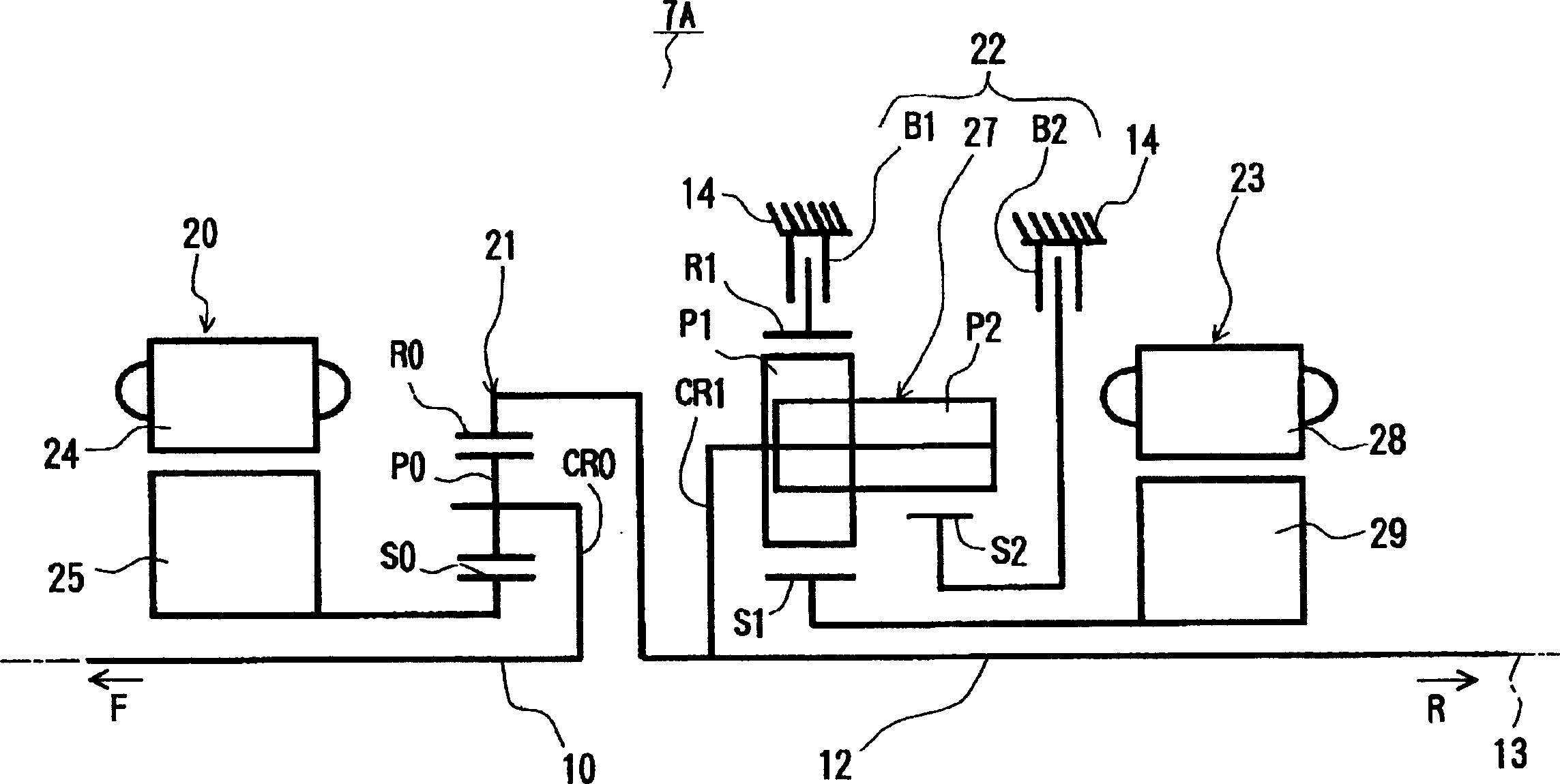
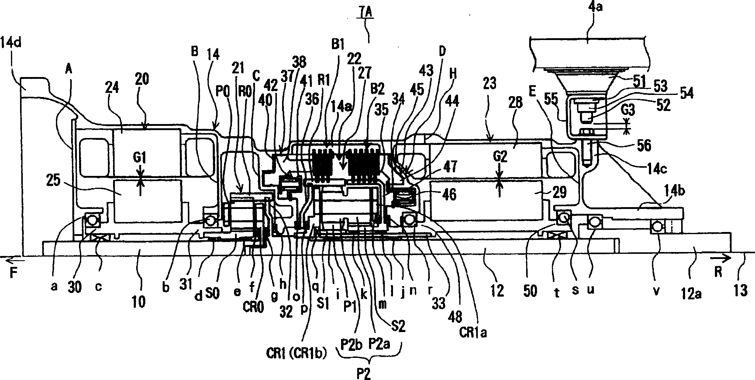
[0134] Next, as a piggyback on figure 1 As another example of the hybrid drive device 7 according to the present invention in the automobile 1 shown, the hybrid drive device 7B according to the present embodiment will be described. First, refer to Figure 7 The skeleton diagram of , illustrating the general situation of the compound drive device 7B as a whole, and then refer to Figure 8 , describe the specific structure in detail. In these figures, the arrow F direction is the front side of the vehicle body (internal combustion engine side), and the arrow R direction is the vehicle body rear side (differential gear side).
[0135] Such as Figure 7 As shown, the compound drive unit 7B moves from close to figure 1 From the internal combustion engine 5 side, that is, from the front side to the rear side, a planetary gear 21 for power distribution, a first electric motor 20, a speed change device 22, and a second electric motor 23 are sequentially arranged. These are accomm...
no. 3 Embodiment approach
[0189] Next, as a piggyback on figure 1 Another example of the hybrid drive device 7 according to the present invention in the automobile 1 shown is a description of the hybrid drive device 7C according to the present embodiment. First, refer to Figure 12 The skeleton diagram of , illustrating the general situation of the compound drive device 7C as a whole, and then refer to Figure 13 , describe the specific structure in detail. In these figures, the arrow F direction is the front side of the vehicle body (internal combustion engine side), and the arrow R direction is the vehicle body rear side (differential gear side).
[0190] Such as Figure 12 As shown, the compound drive unit 7C moves from close to figure 1From the internal combustion engine 5 side, that is, from the front side to the rear side, the second electric motor 23, the speed change device 22, the planetary gear 21 for power distribution, and the first electric motor 20 are sequentially arranged. These ...
PUM
 Abstract
Description
Claims
Application Information
 - R&D
- Intellectual Property
- Life Sciences
- Materials
- Tech Scout
- Unparalleled Data Quality
- Higher Quality Content
- 60% Fewer Hallucinations
Browse by: Latest US Patents, China's latest patents, Technical Efficacy Thesaurus, Application Domain, Technology Topic, Popular Technical Reports.
© 2025 PatSnap. All rights reserved.Legal|Privacy policy|Modern Slavery Act Transparency Statement|Sitemap|About US| Contact US: help@patsnap.com