
Liquid heat storage device of hot water preparator

A heat storage and liquid technology, applied in water heaters, fluid heaters, beverage preparation devices, etc., can solve the problems of difficult control, heat transfer deterioration, etc., and achieve the effect of convenient installation, fewer components, and good heat transfer

Inactive Publication Date: 2010-05-05
BSH BOSCH & SIEMENS HAUSGERAETE GMBH
View PDF5 Cites 0 Cited by
  • Summary
  • Abstract
  • Description
  • Claims
  • Application Information

AI Technical Summary

Problems solved by technology

In this way, an air intermediate cavity is formed between the temperature response element and the inner wall of the protective tube, which causes deterioration of heat transfer and is difficult to control

Method used


Image

  • Liquid heat storage device of hot water preparator
  • Liquid heat storage device of hot water preparator
  • Liquid heat storage device of hot water preparator

Examples


Embodiment Construction

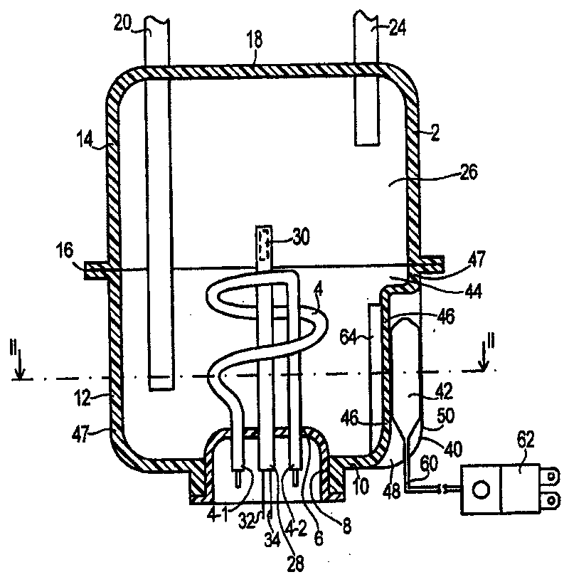
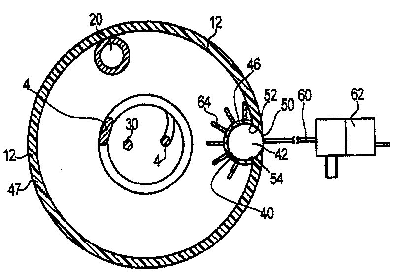
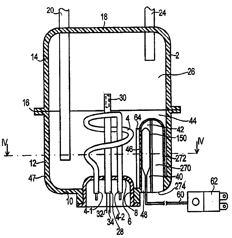
[0022] figure 1 and figure 2 The liquid heat reservoir 2 shown is part of a hot water generator or boiler and contains an electric heating body 4 whose electrical terminals 4-1 and 4-2 pass watertightly through a flange 6 The flange 6 is fitted watertight in a hole 8 in a bottom wall 10 of the container 2.

[0023] The heat storage container 2 consists of a container lower part 12 and a container upper part 14, which are connected to each other in a watertight manner on a parting surface 16 and are each produced by injection molding, for example, from metal or preferably from plastic. A fresh water supply line 20 extends through the container roof wall 18 almost as far as the bottom wall 10 for supplying fresh, cold water on a common water pipe network. The hot water access pipe 24 passes through the container roof wall 18 only to reach immediately below the container roof wall 18 . By opening a cold water switch, fresh water is introduced into the container mouth through ...


PUM


Abstract

The hot water tank of a domestic appliance, e.g. a boiler (2), has a deep and straight holder (40) in the tank wall (10) to take a thermostat (42). A straight and longitudinal gap (50) is formed in the wall (46) of the opening to stabilize the pressure injection molding tool used to form the opening.

Description

technical field [0001] The present invention relates to a liquid heat storage container of a hot water generator. Background technique [0002] German utility model patent G 82 09 111.0 U1 has pointed out a kind of liquid heat accumulator, it has a storage container made of a material with good heat conduction, such as steel, and is welded on the outer surface of the container with a steel Protective tube. Together, these are surrounded by a kind of insulating jacket. [0003] DE-AS 1 259 902 discloses a temperature sensor in a recess on the outer side of a steam boiler tube. The recess is V-shaped in cross section. A temperature sensor in the recess can be welded to the pipe and / or covered by a steel cover welded to the water pipe. [0004] It is also known that a protective tube for accommodating a temperature-responsive element can protrude through a container flange into the liquid heat store. Here, however, the temperature-responsive element must be easily removabl...

Claims


Application Information

Patent Timeline
Patent Type & Authority Patents(China)
IPC IPC(8): F24H9/20B29C45/56A47J31/54B29C33/76B29C45/00B29C45/36F24H1/20F24H9/02F24H9/06F24J2/04
CPCY02B10/20B29C33/76F24H9/2021B29C45/36
Inventor E·克里斯蒂安S·格奥尔格
Owner BSH BOSCH & SIEMENS HAUSGERAETE GMBH
Learn More