
High energy electronic double action machine

A high-energy electronic and compound motor technology, applied in electrical components, electromechanical devices, etc., can solve the problems of inductive load power discount, high raw material cost, small starting torque, etc., to achieve no power harmonic interference, current waveform lag factor is small, The effect of large starting torque

Inactive Publication Date: 2005-11-09
邓建辉
View PDF0 Cites 0 Cited by
  • Summary
  • Abstract
  • Description
  • Claims
  • Application Information

AI Technical Summary

Problems solved by technology

The most commonly used AC motor does not have any energy itself, not only driven by electric energy, but also greatly reduced due to the low power factor of inductive loads
In addition, the rotor of the AC motor is not energized, and the current is induced on the aluminum strip of the rotor after the stator is energized, so the starting torque is small, the shaft power is poor, the work efficiency is low, and the energy consumption is high
Although the DC motor has permanent magnet energy, it uses very little because of the Achilles' heel of the brush.
In addition, the motor can only output high-speed rotating power. For machines that require linear reciprocating power (such as compressor pistons, piston pumps, etc.) , connecting rods, beams, derricks and other conversion devices, after the circular power is converted into linear reciprocating power, the workmanship can be driven to work
Due to the bulky devices such as reducers and derricks, the cost of raw materials is high, and the friction power consumption of transmission at all levels is also high.

Method used


Image

  • High energy electronic double action machine
  • High energy electronic double action machine
  • High energy electronic double action machine

Examples


Embodiment

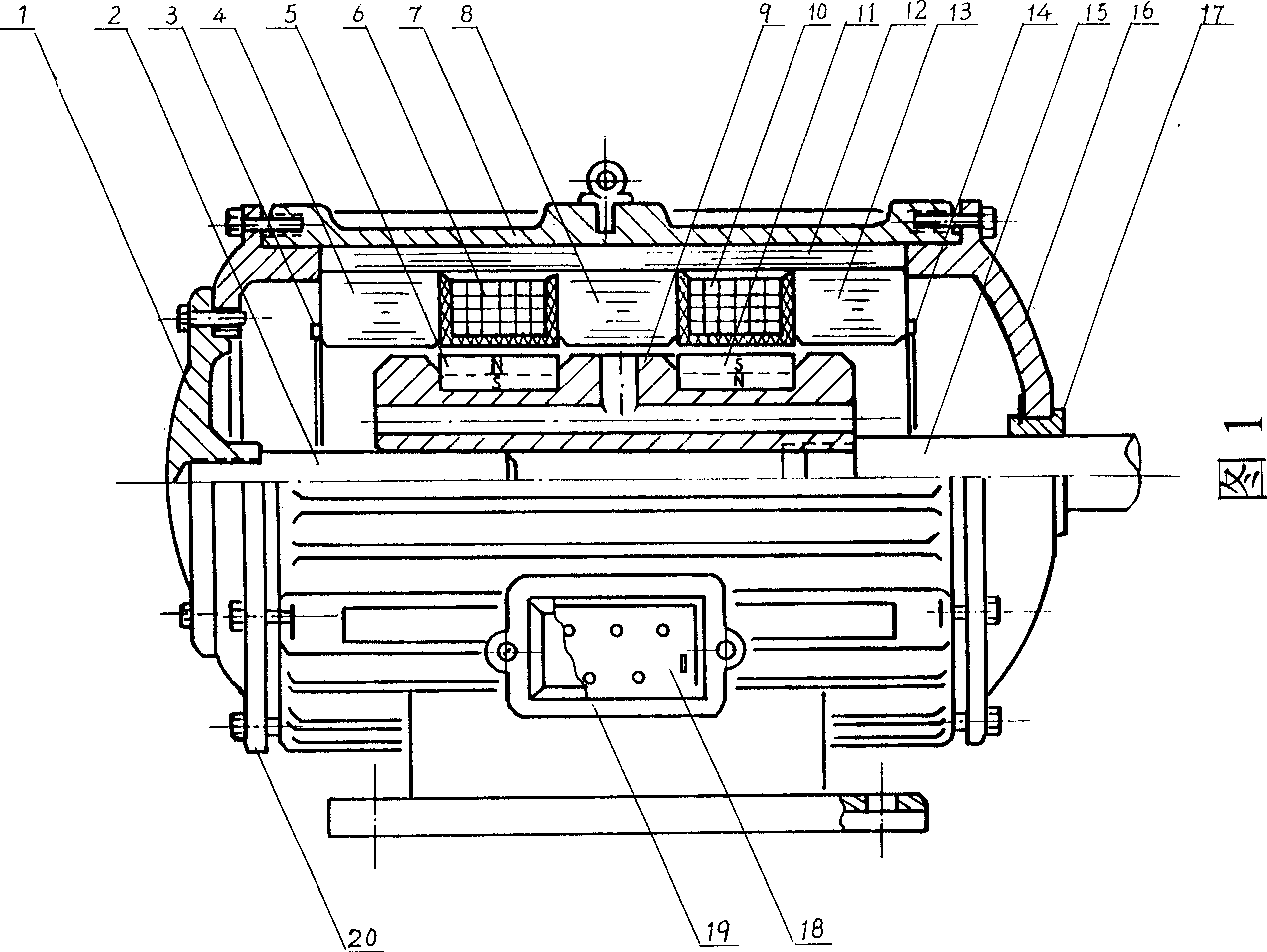
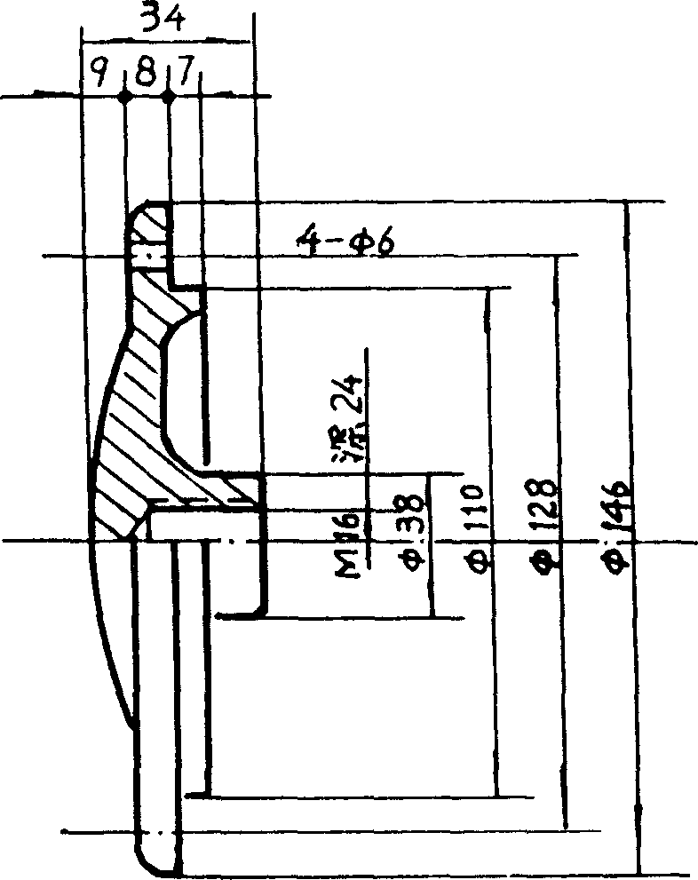
[0032] Fig. 1-16 is a kind of embodiment of high-energy electronic reciprocating machine.

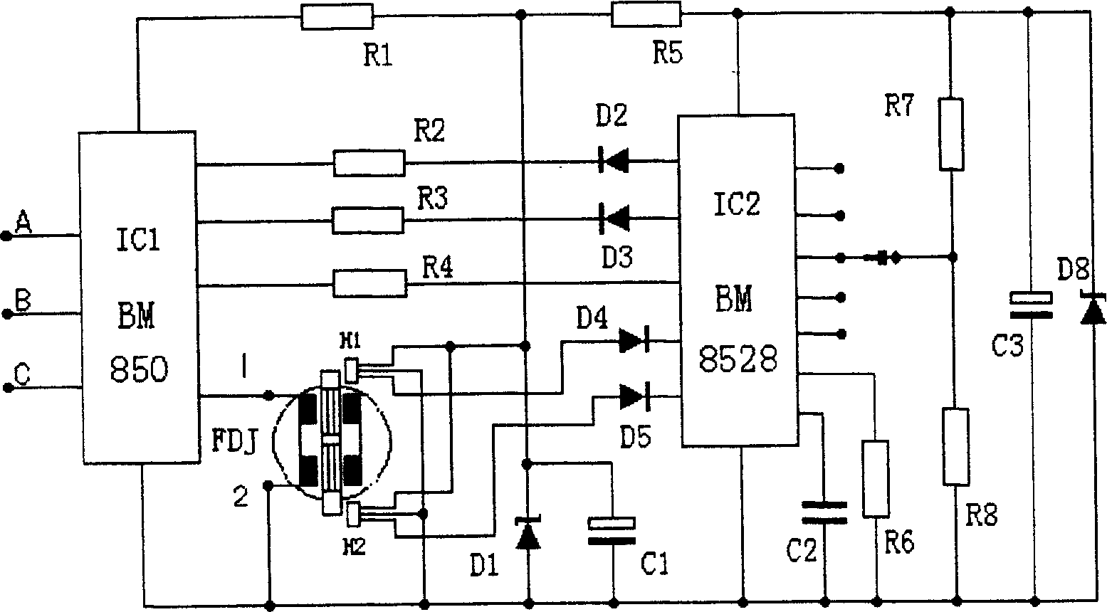
[0033] Implementation: first press Figure 3-15 The requirements of the processing of each component, and according to Figure 16Custom brush circuit board. Then press Figure 1, figure 2 As shown, purchased standard parts and the following electronic components: R1 / 1K, R2 / 4.7K, R3 / 4.7K, R4 / 10K, R5 / 2K, R6 / 7.5K, R7 / 3K, R8 / 5.1K, R9 / 10K, R10 / 10K; C1 / 100 microfarad 25V, C2 / 0.01 microfarad / 63V, C3 / 100 / 16V; D1 / 24V / regulator, D2-5 / 1N4007, D6 / 12V regulator, H1 , H2 / magnetic control device, IC1 / BM850 / special commutation module, IC2 / BM8525 / special frequency conversion processing circuit, FDJ / complex machine. At the same time, refer to Figure 7 As shown, the wire is wound on the winding frame: wire number 1.12, layered and densely wound 800 turns, and the layers are insulated with glass fiber tarpaulin. Referring to the overall structural relationship in Figure 1, follow the steps below to ...


PUM


Abstract

A high efficient direct line to-and-fro power machine developing magnet energy, replacing and saving electric energy takes the physical energy source stored in the magnet materials as the runner and uses a little conversion pulse current to make excitation for the stator to obtain direct line to-and-fro power much larger than electric energy. The machine applies pulse supply to increase power factor and shaft power and operates on either two-phase or three- phase.

Description

Technical field [0001] The invention relates to the field of power machinery manufacturing, in particular to the development and application of new energy linear reciprocating power machinery. Background technique [0002] The prior art in the prior art field of the present invention is: various AC and DC motors and electromagnetic compressors that convert electric energy into rotational power. Among them, the electromagnetic compressor has long been eliminated due to the fatal contradiction between frequency response and power consumption. The most commonly used AC motor does not have any energy source itself, not only driven by electric energy, but also greatly compromised by the low power factor of inductive loads. In addition, the rotor of the AC motor is not energized, and the stator is energized to induce current on the rotor aluminum strip, so the starting torque is small, the shaft power is poor, the work efficiency is low, and the energy consumption is high. Altho...

Claims


Application Information

Patent Timeline
Patent Type & Authority Applications(China)
IPC IPC(8): H02K33/18
Inventor 邓建辉
Owner 邓建辉
Learn More