Portable accoustic apparatus

A kind of audio equipment, portable technology, applied in the field of portable audio equipment

Inactive Publication Date: 2005-11-02
MITSUBISHI ELECTRIC CORP
View PDF5 Cites 2 Cited by
  • Summary
  • Abstract
  • Description
  • Claims
  • Application Information

AI Technical Summary

Problems solved by technology

Although it depends on the shape or material of the box body 6, a small gap between the box body 6 and the ear hole 22 produces a

Method used


Image

  • Portable accoustic apparatus
  • Portable accoustic apparatus
  • Portable accoustic apparatus

Examples


Embodiment Construction

[0025] Hereinafter, in order to describe the present invention in more detail, the best mode for carrying out the present invention will be described with reference to the drawings.

[0026] Embodiment 1

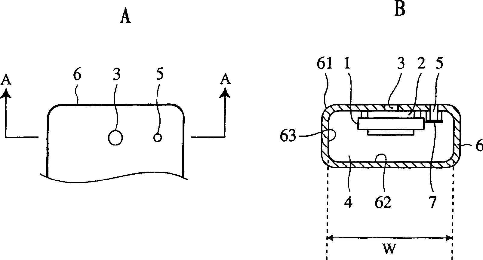
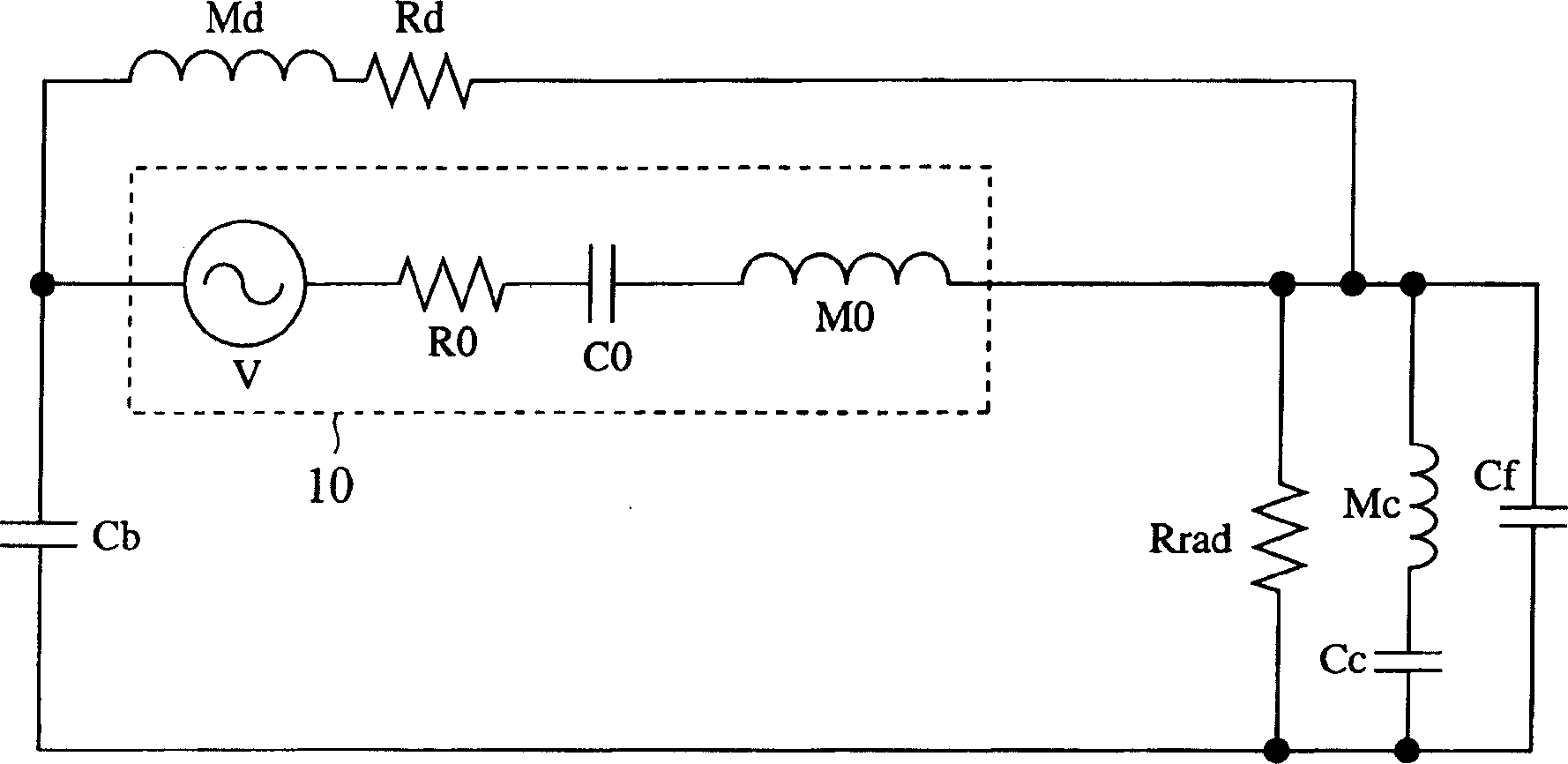
[0027] figure 1 A and 1B are a front view and a sectional view showing a partial structure of the portable audio device according to Embodiment 1 of the present invention. figure 2 A and B are shown figure 1 An explanatory diagram of the use state of the portable audio equipment shown, image 3 is shown with figure 1 as well as figure 2The circuit diagram of the corresponding acoustic equivalent circuit. In addition, in each figure, with Figure 6 to Figure 8 The same or corresponding parts are denoted by the same symbols.

[0028] figure 1 In Fig. 1 , the acoustic conversion element 1 is supported and fixed inside the sound emission hole 3 of the casing 6 of the portable audio device. The box body 6 has a cylindrical or polygonal cylindrical peripheral outer ...


PUM


Abstract

A portable acoustic apparatus includes a sound outlet ( 3 ) formed in the front wall ( 61 ) of a housing ( 6 ); an acoustic converting element ( 1 ) fixed in the housing in such a manner that a front chamber ( 2 ) is formed between the acoustic converting element and the front wall ( 61 ), and a back chamber ( 4 ) is formed between the acoustic converting element and the back wall ( 62 ) of the housing ( 6 ); and a duct ( 5 ) that is formed in the front wall ( 61 ) around the sound outlet ( 3 ) and communicates to the outside of the housing. The minimum inner width W of the outer casing ( 63 ) of the housing ( 6 ) is made equal to or less than the standard diameter of the human concha.

Description

technical field [0001] The present invention is designed to be a portable audio device of a portable phone that the user presses the sound emitting hole to the concha cavity (concha: outer ear) part to listen to. Background technique [0002] As a component installed in portable audio equipment such as portable telephones, small wireless communicators, small portable radios, and small recording and reproducing machines to play the role of receiver (receiver) or speaker, there are audio signals that are input to the audio conversion element and converted into voice. Receiver audio components for sound output such as music and music. In the portable audio equipment using this receiving audio component, the user presses the sound emitting hole (also referred to as the receiver port in the mobile phone) provided on the equipment casing to the ear shell when listening to the sound. cavity section. Generally, when mounting a receiving audio component on a portable audio device, ...

Claims


Application Information

Patent Timeline
Patent Type & Authority Applications(China)
IPC IPC(8): H04M1/03H04R1/10H04R1/28
CPCH04M1/03H04M1/035H04R2499/11
Inventor 松冈文启水谷保恭
Owner MITSUBISHI ELECTRIC CORP
Why Eureka
Try Eureka