
Valve of underground well for controlling gas

A ground well and air control technology, which is applied in the direction of lifting valve, valve details, valve device, etc., can solve the problems of insufficient lubrication of the pull rod, increased trouble, inconvenient construction, etc., and achieve the effect of reasonable structural design, easy opening, and convenient installation

Inactive Publication Date: 2005-10-26
程伟强
View PDF1 Cites 4 Cited by
  • Summary
  • Abstract
  • Description
  • Claims
  • Application Information

AI Technical Summary

Problems solved by technology

[0006] 2. It is necessary to manually switch the well valve. When opening, pull up the switch lever and hook the pull rope (easy to pull when closing or pulling in an emergency); pull the pull rope when closing, and it cannot close the well valve in the following situations: 1. If the ground well valve is scratched, the valve body just tilts to the side of the pull rope, pressing or breaking the rope
3. The pull rope hook is pulled off or the pull rope is broken. If there is an emergency and it needs to be closed, it will lose its function
4. In the rainy season, sometimes the pull rod that is pulled up is not lubricated enough. Even if the pull rope is pulled, the pull rod cannot return to its position, and the valve body is still in the normally open state.
5. When injecting oil, the pull rope is easily absorbed by the oil
In addition, the burden on the first-line refueling personnel is increased, and the operation is very complicated. This is because 1) it must be fastened to the ground well valve switch before refueling; 2) it must be unloaded after refueling and recycled to On the car; 3) During refueling, the refueling personnel should stand under the fuel tank gauge of the aircraft, observe the refueling volume, and balance the fuel tank of the aircraft. If the personnel accidentally touch it or pull it accidentally, the valve will be closed, and the refueling personnel will have to go to the well valve to open it again, which adds a lot of trouble
[0007] 3. The depth of the ground well reaches about 60cm, and its installation, maintenance and maintenance are difficult
[0010] 1. The investment is large and the construction is inconvenient, especially the reconstruction of the already built airport is limited to a certain extent
[0011] 2. It cannot guarantee that there is a corresponding control switch for each well position, and there is still a certain distance, ranging from 20-30 meters to hundreds of meters, which cannot cope with emergency situations
When the refueling personnel are nervous, they may not remember that there is this control switch, but once there is an emergency situation of fuel injection, every second counts
[0012] 3. Too many switches, long lines, difficult to manage
When the line or circuit fails, the system will not be able to function but will bring negative effects, resulting in the possibility of paralysis of the entire oil supply system
If the fuel cannot be supplied, the airport will face the embarrassing situation that the plane can land but fly out without fuel

Method used


Image

  • Valve of underground well for controlling gas
  • Valve of underground well for controlling gas
  • Valve of underground well for controlling gas

Examples


Embodiment 1

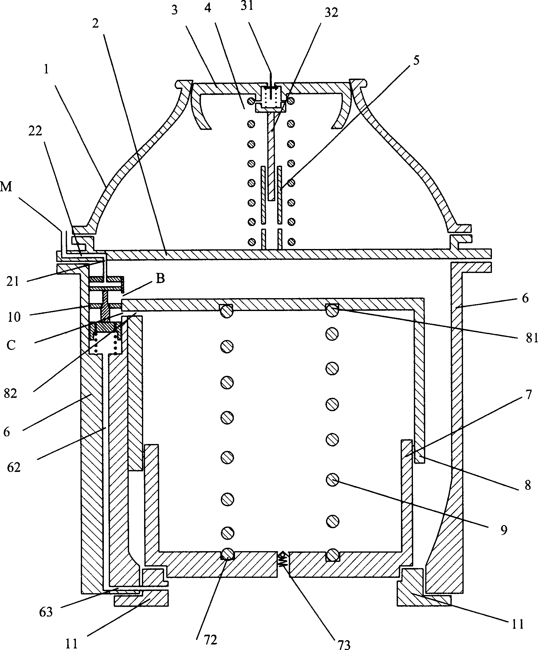
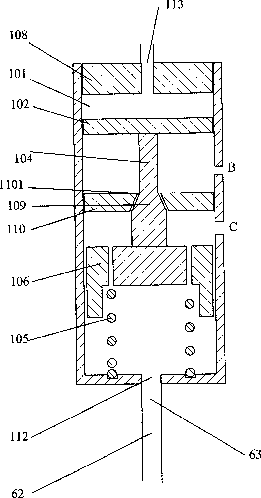
[0031] Such as figure 1 , Shown in 2, the present invention is provided with joint valve, main valve, air control valve and pressure device valve. The joint valve is provided with a joint valve body 1, a joint valve base 2, a guide piston 3, a guide piston spring 4 and a guide piston spring seat 5. The joint valve base 2 is connected, the guide piston 3 is arranged in the joint valve body 1, the piston rod 32 of the guide piston 3 is inserted into the guide piston spring seat 5, and the guide piston spring seat 5 is fixed on the center of the upper surface of the joint valve base 2, and the guide piston The spring 4 is sleeved on the piston rod 32 of the pilot piston 3 and the spring seat 5 of the pilot piston. A pressure device valve 31 is provided on top of the pilot piston 3 .

[0032] The main valve is provided with a main valve body 6, a main piston 7, a main piston sleeve 8, a main piston spring 9 and a main valve seat 11. The top of the main valve body 6 is integrate...

Embodiment 2

[0036] Such as figure 1 , 2, similar to Embodiment 1, the difference is that the main valve body 6 and the joint valve are separated into two independent parts.

Embodiment 3

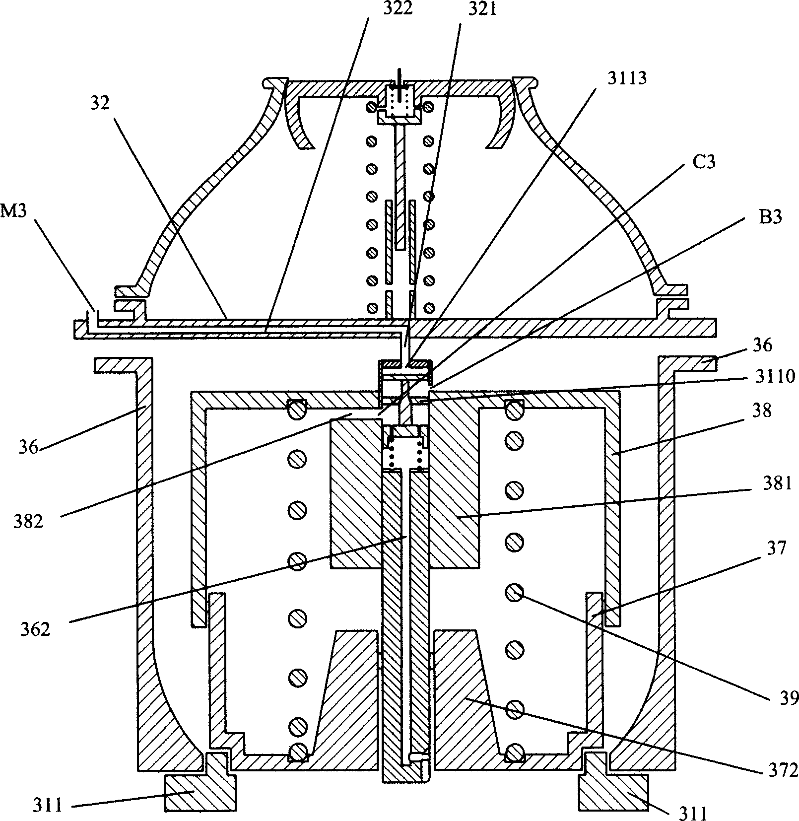
[0038] Such as image 3 As shown, similar to Embodiment 1, the difference is that the air control valve is arranged on the main piston sleeve 38 in the inner cavity of the main valve body 36, and the oil inlet passage through the oil inlet hole at the bottom of the cylinder body of the cylinder is the same as that arranged on the main piston. The channel 362 of the inner cavity of the sleeve 38 is connected, and the channel 362 of the inner cavity of the main piston sleeve 38 is communicated with the oil pipeline connected to the bottom of the main valve seat 311 below the main piston 37 and the main valve body 36, and the oil hole 382 of the main piston sleeve 38 It is located below the top of the main piston sleeve 38 . The oil hole B3 set on the cylinder wall between the piston and the cylinder inner wall baffle communicates with the inner cavity of the main valve body 36, and the oil hole C3 set on the cylinder wall below the cylinder inner baffle 3110 communicates with th...


PUM


Abstract

The invention relates to the gas-controlled ground well valve, which comprises the interface valve, the main valve and the gas-controlling valve. The interface valve connects the interface base, the guide piston pole inserts in the guide piston spring base, and the guide piston spring is sleeved outside of the piston pole and the spring base; the main piston of the main valve is on the bottom of the main valve base, and the main piston sleeve is outside of the main piston, the main piston springs is between the spring bases, and the side walls of the main piston sleeve have the oil apertures; the gas-control valve piston is at the upper part of the cylinder, the top of the connecting rod connects the bottom of the piston, and the bottom of the connecting rod joints the spring locating sleeve with the oil apertures; the inner wall of the cylinder has the baffle with its central aperture connecting the middle of the connecting rod; the spring locating slot is at the bottom of the cylinder; the oil inlet aperture at the bottom of the cylinder connects the oil transferring pipe; the spring is between the locating sleeve and the locating slot; the oil aperture on the cylinder wall communicates with the main valve chamber; the oil aperture is below the baffle of the cylinder; the air-through hole connects the inlet hole through the air pipe and the interface valve base.

Description

technical field [0001] The invention relates to a valve, in particular to a well valve which is mainly used in a refueling system and adopts air control. Background technique [0002] Taking the airport as an example, the refueling system is one of its important equipment. Its structural design and quality are related to the safety of passengers, aircraft and airport facilities. Among them, the well valve is an important part of the plug-type refueling system. The interface for the fuel output of the apron pipe network system. [0003] Existing ground well valve is made up of main piston, main piston spring, inspection valve (filter screen), pilot piston, pilot valve, pressure device valve, maintenance valve, pull rod and housing etc. Beijing: China Legal Publishing House, 2000, 347-348). When the well joint of the pipeline refueling truck is connected to the well valve, the end face of the well joint switch contacts the pressure relief device on the top of the well valve,...

Claims


Application Information

Patent Timeline
Patent Type & Authority Applications(China)
IPC IPC(8): F16K1/00
Inventor 程伟强
Owner 程伟强
Learn More