
Paper feeding box, printer and method for using paper feeding box

A technology for printing devices and paper feeding, which is applied in printing devices, printing, transportation, and packaging, and can solve the problems of increasing the number of overall components, increasing manufacturing complexity, and the inability to reduce the manufacturing cost of paper trays, etc.

Inactive Publication Date: 2005-10-19
QUISDA CORP
View PDF0 Cites 2 Cited by
  • Summary
  • Abstract
  • Description
  • Claims
  • Application Information

AI Technical Summary

Problems solved by technology

[0003] However, having both a locking mechanism and an opening mechanism on the existing paper tray will increase the complexity of its manufacture, and because the setting of the locking mechanism and the opening mechanism will increase the number of overall components, the existing paper tray The manufacturing cost of the

Method used


Image

  • Paper feeding box, printer and method for using paper feeding box
  • Paper feeding box, printer and method for using paper feeding box
  • Paper feeding box, printer and method for using paper feeding box

Examples


Embodiment Construction

[0020] The preferred embodiments of the present invention are described below with reference to the drawings.

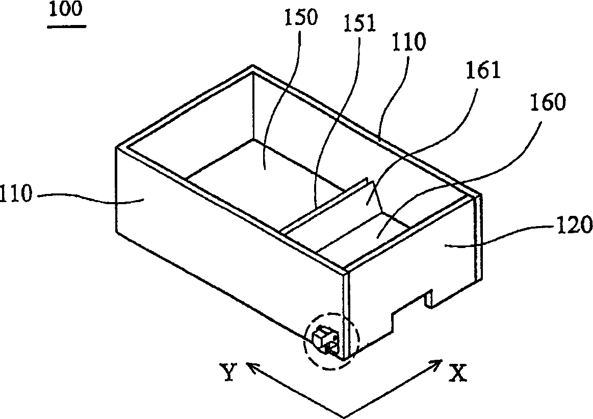
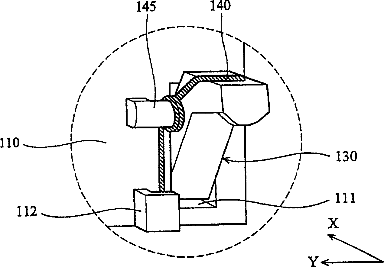
[0021] see figure 1 and figure 2 , the paper tray 100 of the present invention can be combined with a printing device (not shown), and it is mainly composed of two side walls 110, a door panel 120, a rotating assembly 130, an elastic assembly 140, a fixing pin 145, a main The paper tray part 150 and an auxiliary paper tray part 160 are formed.

[0022] Such as figure 1 As shown, the auxiliary paper tray part 160 is located between the main paper tray part 150 and the door panel 120 , and paper can be placed in the auxiliary paper tray part 160 and the main paper tray part 150 . In addition, the printing device also has a paper inlet (not shown), and the auxiliary paper tray part 160 and the main paper tray part 150 also have a paper output baffle 161 and a paper output baffle 151 respectively, the paper output baffle 161 and 151 are adjacent to each other. When...


PUM


Abstract

One kind of paper feeding box may be combined with one printing unit and the printing unit has one lug. The paper feeding box includes one side wall with one through hole, one door leaf, one rotating assembly and one elastic assembly. The door leaf is pivoted to the side wall and can rotate around one X-axle. The rotating assembly is set inside the through hole and pivoted to the side wall, and can rotate optionally around one Y-axle between one first position and one second position. There is one preset angle between the X-axle and the Y-axle. The elastic assembly is set between the rotating assembly and the side wall and provides one elastic force for the rotating assembly to rotate towards the first position.

Description

technical field [0001] The invention relates to a paper tray, in particular to a paper tray which is easier to lock and open. Background technique [0002] Generally speaking, most of the current printing devices such as printers are developing toward miniaturization. Therefore, in order to reduce the volume of the printer, among the paper trays of the printer, the main paper tray part and the auxiliary paper tray part (Multi-purpose tray part) are usually combined into one design. At the same time, under this design, when the paper tray is taken out of the printer, its auxiliary tray part is used as the handle of the tray, and when the tray is in the printer, its auxiliary tray The part can be opened and carry paper according to the demand. As mentioned above, in order to cope with such a design, when the auxiliary paper tray is used as a handle, the fixing force required by the auxiliary paper tray must be as large as possible, so as to facilitate the user to take out th...

Claims


Application Information

Patent Timeline
IPC IPC(8): B41J13/10B65H5/00
Inventor 林年进
Owner QUISDA CORP
Learn More