
Test tube rotation mechanism and test tube rotation code scanning device

A technology of a rotating mechanism and a test tube, applied in the field of medical devices, can solve the problems of complex structure, high manufacturing cost, inconvenient use, etc., and achieve the effects of avoiding too small friction force, simple structure and increasing friction force

Active Publication Date: 2020-12-08
DIRUI MEDICAL TECH CO LTD
View PDF6 Cites 0 Cited by
  • Summary
  • Abstract
  • Description
  • Claims
  • Application Information

AI Technical Summary

Problems solved by technology

[0004] In view of the above deficiencies in the prior art, the purpose of the present invention is to provide a test tube rotation mechanism and a test tube rotation code scanning device, aiming to solve the problems of inconvenient use, complex structure and high manufacturing cost of the existing blood collection test tube barcode reading device

Method used


Image

  • Test tube rotation mechanism and test tube rotation code scanning device
  • Test tube rotation mechanism and test tube rotation code scanning device
  • Test tube rotation mechanism and test tube rotation code scanning device

Examples


Embodiment Construction

[0027] The present invention provides a test tube rotating mechanism and a test tube rotating code scanning device. In order to make the purpose, technical solution and effect of the present invention clearer and clearer, the present invention will be further described in detail below. It should be understood that the specific embodiments described here are only used to explain the present invention, not to limit the present invention.

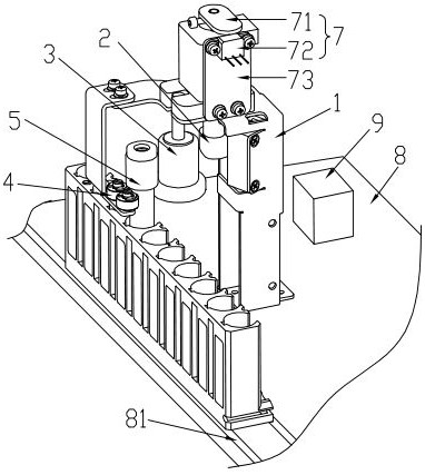
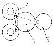
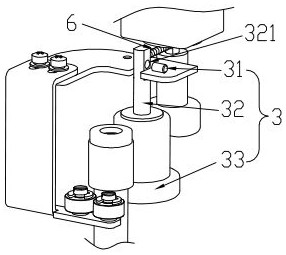
[0028] The present invention provides a preferred embodiment of the test tube rotation mechanism, such as figure 1 , figure 2 As shown, it includes a bracket 1, a driving part 2, a transmission part 3 and a limiting part 4 which are respectively fixed on the bracket and whose axes are all in the vertical direction; the limiting part is tangent to the test tube 5 at two first tangent points A and B, the transmission part is tangent to the test tube at a second tangent point C, the second tangent point and the two first tangent points are loca...


PUM


Abstract

The present invention discloses a test tube rotation mechanism and a test tube rotation scanning code device. The test tube rotation mechanism comprises a support, and a drive portion, a transmissionportion and a spacing portion which are fixed on the support and have axes being in a vertical direction; the spacing portion and a test tube are tangent at two first tangent points, the transmissionportion and the test tube are tangent at a second tangent point, the second tangent point and the two first tangent points are located in the same horizontal plane, and the ligatures of the second tangent point and the two first tangent points form an isosceles triangle, and the second tangent point is located at the vertex angle of the isosceles triangle; and the transmission portion rotates under the driving of the drive portion and is configured to perform friction of the test tube at the second tangent point, the test tube is passively rotated under the action of the friction, and the spacing portion is subjected to friction through the first tangent points to drive the rotation of the spacing portion. The test tube rotation mechanism is convenient to use and simple in structure, the three tangent points are used to fix the test tube to form a certain holding force to the test tube so as to increase the friction between the transmission portion and the test tube and ensure the rotation of the test tube.

Description

technical field [0001] The invention relates to the technical field of medical devices, in particular to a test tube rotation mechanism and a test tube rotation code scanning device. Background technique [0002] At present, the barcode reading of blood collection test tubes in hospitals is mostly scanned manually, which is not only a heavy workload, but also prone to errors. In order to solve the above problems, researchers have developed some code scanning devices, which are mainly divided into two types: the barcode fixed position reading method and the barcode mobile reading method. Among them, the fixed type is more commonly used. Its advantages are simple structure and low cost. The disadvantage is that it has higher requirements for barcode pasting and poor error tolerance. The disadvantages of the barcode mobile reading method are: the existing device has a complex structure, poor reliability, and usually uses a cylinder drive method, which has high manufacturing co...

Claims


Application Information

Patent Timeline
Patent Type & Authority Patents(China)
IPC IPC(8): G06K7/10
CPCG06K7/10415
Inventor 侯建文张勋郭敬满郑国明
Owner DIRUI MEDICAL TECH CO LTD
Learn More