
Illuminant brightness control device for optical mouse

A technology for controlling device and light source brightness, which is applied in the field of optical mouse, and can solve problems such as large instantaneous current consumption, long shutter time, and inability to realize motion wake-up

Inactive Publication Date: 2005-09-14
SUNPLUS TECH CO LTD
View PDF0 Cites 3 Cited by
  • Summary
  • Abstract
  • Description
  • Claims
  • Application Information

AI Technical Summary

Problems solved by technology

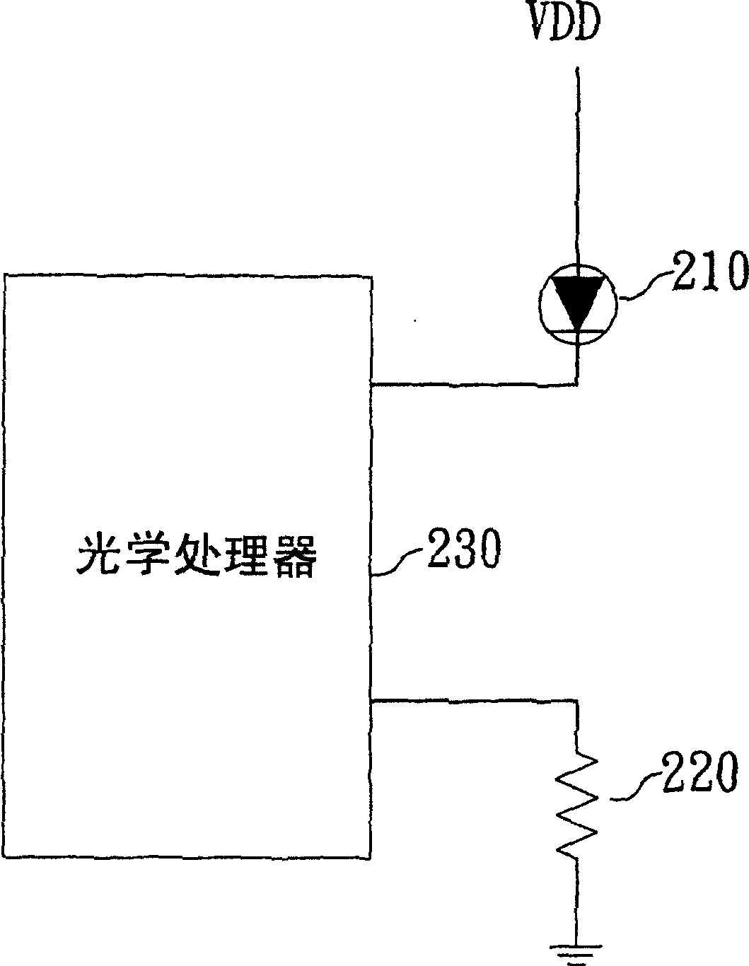
[0003] With the aforementioned optical mouse, when the resistor 220 is soldered to the circuit board, the amount of current flowing through the light source 210 is fixed, that is, the brightness of the light source 210 cannot be adjusted flexibly.
When the sensing sensitivity of the optical processor 230 is very high and is very sensitive to light, since the lighting of the light source 210 continues during the period when the shutter is opened or even during the entire optical mouse use (Acttve), it may cause even if the shutter cannot be activated. Zooming out again, the image sensed by the optical processor 230 is still saturated, which leads to the inability of the optical mouse to perform relevant detection.
[0004] In addition, the aforementioned mouse needs a longer shutter time to image when facing a darker image, because of the requirement of processing speed, the brightness of the light source 210 must maintain a certain high brightness. In the suspend state (USB Suspend current specification limit is 500uA), and turning on the light source 210 for a long time leads to failure to comply with relevant current limit specifications, so the aforementioned mouse in the prior art will not be able to perform motion detection in the Suspend state, and cannot realize the motion wakeup (Motion Wakeup) function
[0005] In addition, because the light source 210 is turned on and off, the instantaneous current consumption will be too large, which will easily generate noise
like image 3 As shown in , the current flowing through the light source 210, when the light source 210 is turned on and off (at A, B), there will be an over-shooting phenomenon (over-shooting and under-shooting), which is likely to cause the optical mouse to malfunction due to the difference in image formation. Misoperation

Method used


Image

  • Illuminant brightness control device for optical mouse
  • Illuminant brightness control device for optical mouse
  • Illuminant brightness control device for optical mouse

Examples


Embodiment Construction

[0020] For preferred embodiments of the optical mouse LED control method and device of the present invention, please refer to Figure 4 The circuit diagram shown includes a light source 410, a current switch device 420 and a control device 430, wherein the light source 410 is preferably a light emitting diode (LED). The LED 410 is used to illuminate the sampling plane of the mouse, its anode is connected to a high potential, and its cathode is connected to the current switch device 420 . The current switch device 420 has a plurality of switch devices, and each switch device is individually coupled to the light source 410 to provide a current to flow through the light source 410 when a switch device is turned on. And, the control device 430 is coupled to the current control device 420 to control whether the plurality of switch devices of the current control device 420 are turned on or not, so as to control the magnitude of the current flowing through the light source 410 .

[...


PUM


Abstract

The invention relates to an optical mouse light source brightness control apparatus comprising light source, a current switch apparatus and a control apparatus.Light source is to illuminate sampling plane of a mouse and current switch apparatus is set with multiple switches, each of which is coupled to light source, then, when a switch apparatus is conducted, the current passing by light source is changed; besides, the apparatus uses multiple switches conduction state of current control apparatus to control current passing by light source and brightness of light source.

Description

technical field [0001] The invention relates to the technical field of an optical mouse, in particular to a brightness control device for an optical mouse light source. Background technique [0002] In a general existing optical mouse, a light-emitting diode (LED) is used to irradiate the mouse pad or other objects with light, and then an image sensor retrieves the image frame (Frame) on the mouse pad, and compares the front and rear images to obtain the result. Get the movement vector of the optical mouse, and pass to determine the direction and distance of the optical mouse movement. figure 1 It is a circuit block diagram of an existing optical mouse, which includes a light source 210 , a resistor 220 and an optical processor 230 . The light source 210 is a light emitting diode (LED). The value of the resistor 220 is used to adjust the amount of current flowing through the light source 210 to determine the brightness of the light source 210 . There are mainly two ways fo...

Claims


Application Information

Patent Timeline
IPC IPC(8): G06F3/038
Inventor 林家骏
Owner SUNPLUS TECH CO LTD
Learn More