Grooved forming roll

A forming roll and grooved technology, which is applied in the direction of textiles and papermaking, papermaking, paper machine wet end, etc., can solve the problems of streaks and other problems

Active Publication Date: 2005-08-17
METSO PAPER INC
View PDF0 Cites 3 Cited by
  • Summary
  • Abstract
  • Description
  • Claims
  • Application Information

AI Technical Summary

Problems solved by technology

In this case there is a problem of streaking due to the fact that the flow rate of the water is not the same at different positions of the forming roll

Method used


Image

  • Grooved forming roll
  • Grooved forming roll
  • Grooved forming roll

Examples


Embodiment Construction

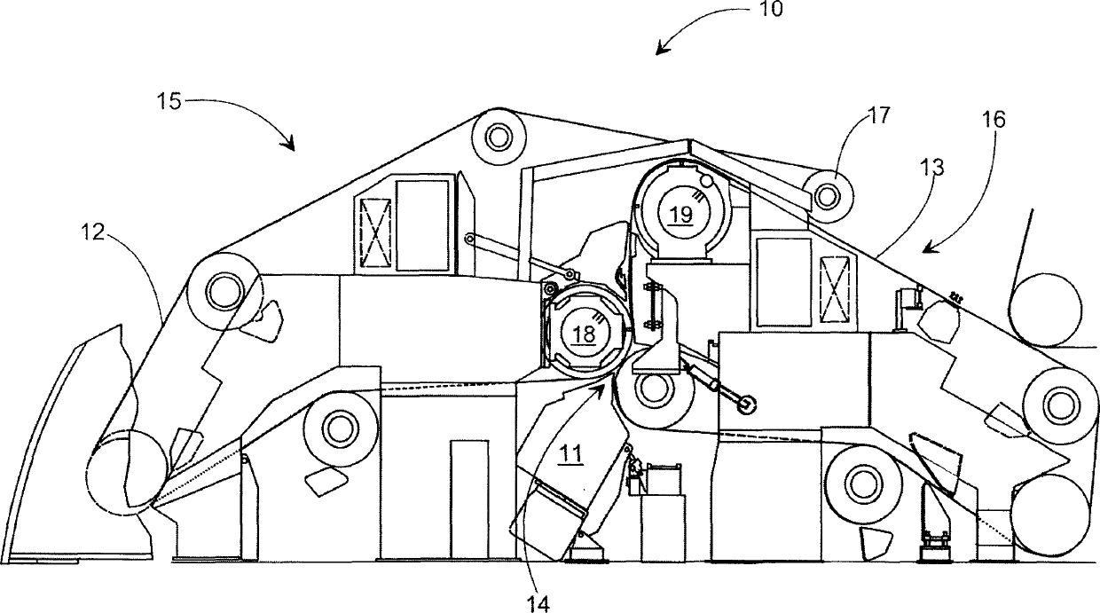
[0018] Figure 1 shows the forming section 10 of a paper machine of known configuration. The forming section 10 is here arranged as a gap former, in which the stock suspension is fed from the headbox 11 to the gap 14 formed by the two fabrics 12 and 13 . The wires 12 and 13 formed into two closed loops are supported in the forming section 10 by aligned roll packs 15 and 16 . In practice, the webs 12 and 13 travel a distance in intimate contact with the web remaining between them. This distance begins at the nip 14 and ends at the return roll 17 of the wire 12 . The return roller 17 is supported above the inner wire 13 . This roll pack 15 of the outer wire also includes a forming roll 18 shared between the roll packs 15 and 16, starting from the nip 14 . This forming roll is also referred to as the first couch roll. The second couch roll 19 is also shared between the roll assembly parts 15 and 16 .

[0019] The forming rolls according to the invention are used in the formin...


PUM


Abstract

A grooved forming roll in a paper machine has a rotably supported shell ( 20 ) with circular openings ( 21 ) arranged to be open at least on the outer surface of the shell ( 20 ). Each opening ( 21 ) has a circular groove is formed on the outer surface arranged concentrically relative to the opening ( 21 ). A portion of the formed circular openings ( 22 ) extends to each opening ( 21 ) from each adjacent opening ( 21 ). The outer radius (r) of the circular groove ( 22 ) is arranged such that the number of necks ( 24 ), delimited by the adjacent openings ( 21 ) and their circular grooves ( 22 ) on the shell outer surface within the area of one circular groove ( 22 ), is greater than the number of the adjacent openings ( 21 ) of the corresponding opening ( 21 ).

Description

technical field [0001] The present invention relates to a grooved forming roll comprising a rotatably supported housing comprising at least circular openings opening on the outer surface of the housing, and associated with each opening formed on the outer surface An annular groove on the upper surface, the annular groove being concentric with the corresponding opening, on the outer surface, a portion of the annular groove being formed extending from each opening to each adjacent opening. Background technique [0002] Publication No. 9932713 of the World Intellectual Property Organization (WO) discloses a forming roll, especially the design of its outer surface. Its purpose is to increase the open surface of the housing to avoid the previously used metal mesh. Previously, a plastic metal mesh was placed on top of the forming roll by shrinkage and in use the mesh wore very quickly. Another problem is curling and dirtying of metal mesh. Metal mesh also limits the chemicals a...

Claims


Application Information

Patent Timeline
Patent Type & Authority Applications(China)
IPC IPC(8): D21F1/40D21F3/10
CPCD21F3/105
Inventor 尤哈尼·韦斯托拉海基·卡尔图宁
Owner METSO PAPER INC
Why Eureka
Try Eureka