
Pneumatic toggle type battery plastic cover pressing method

A technology of pneumatic toggle lever and plastic cover, which is applied in the direction of battery pack parts, circuits, electrical components, etc., can solve the problems of high maintenance cost, high power consumption of the device, and large maintenance volume, and achieve reduced maintenance cost and good stability , The effect of maintenance reduction

Inactive Publication Date: 2005-08-03
王贤正
View PDF0 Cites 0 Cited by
  • Summary
  • Abstract
  • Description
  • Claims
  • Application Information

AI Technical Summary

Problems solved by technology

[0002] At present, my country's dry battery industry produces a large # When the plastic cover of the battery is used, the pressing device used is a 1.5KW motor, which is decelerated by the first-stage bridge belt, and then driven by the small pulley to drive the large flywheel for the second deceleration, and then a The cam, which presses the lower roller to transmit the pressing force, such a device consumes a lot of power, the mechanical transmission is complicated, the work efficiency is not high, and there is a large pressure on the force point, the force is not easy to balance, and the maintenance is large. Disadvantages of high maintenance costs

Method used


Image

  • Pneumatic toggle type battery plastic cover pressing method
  • Pneumatic toggle type battery plastic cover pressing method
  • Pneumatic toggle type battery plastic cover pressing method

Examples


Embodiment Construction

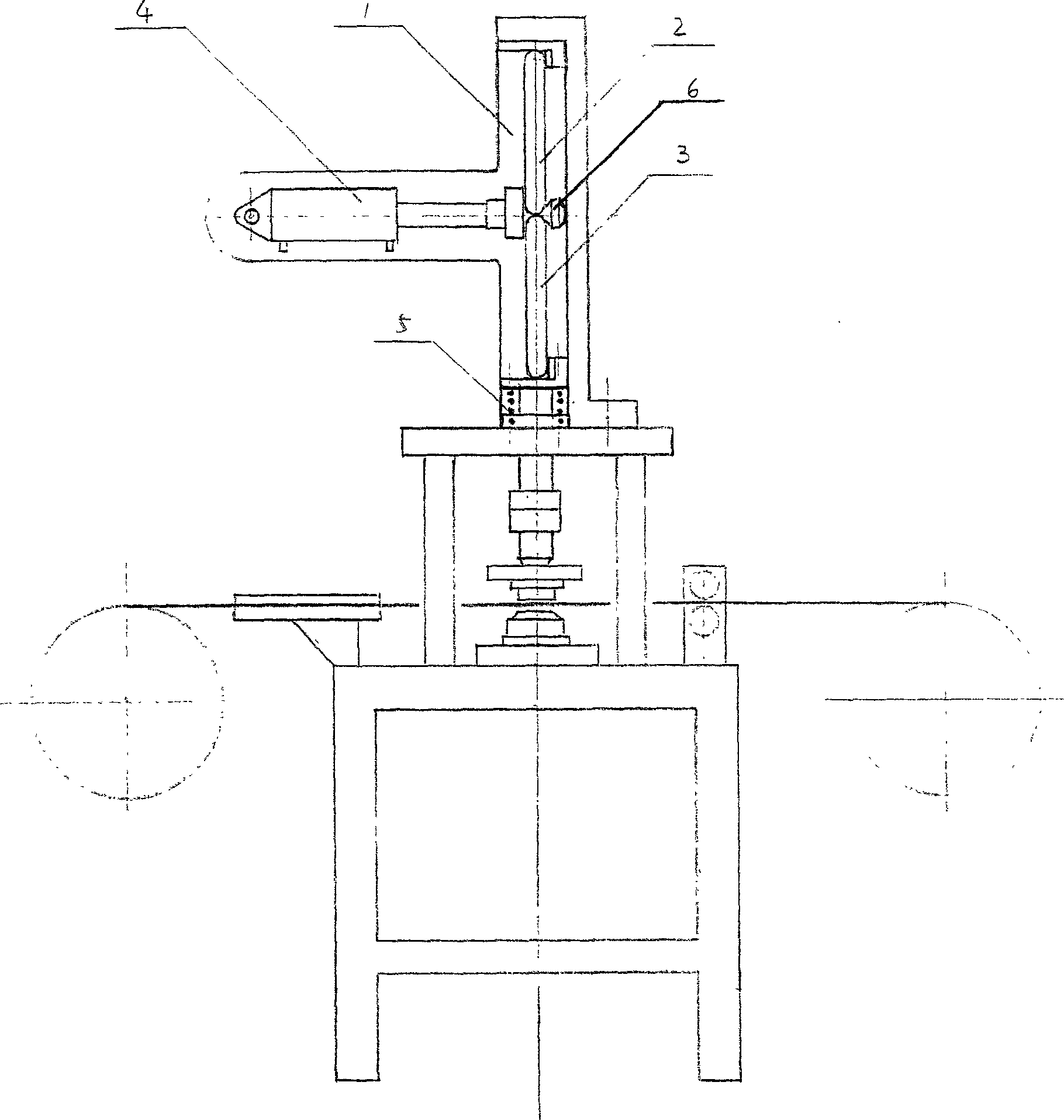
[0022] Specific embodiments of the present invention will be described in detail below in conjunction with the accompanying drawings.

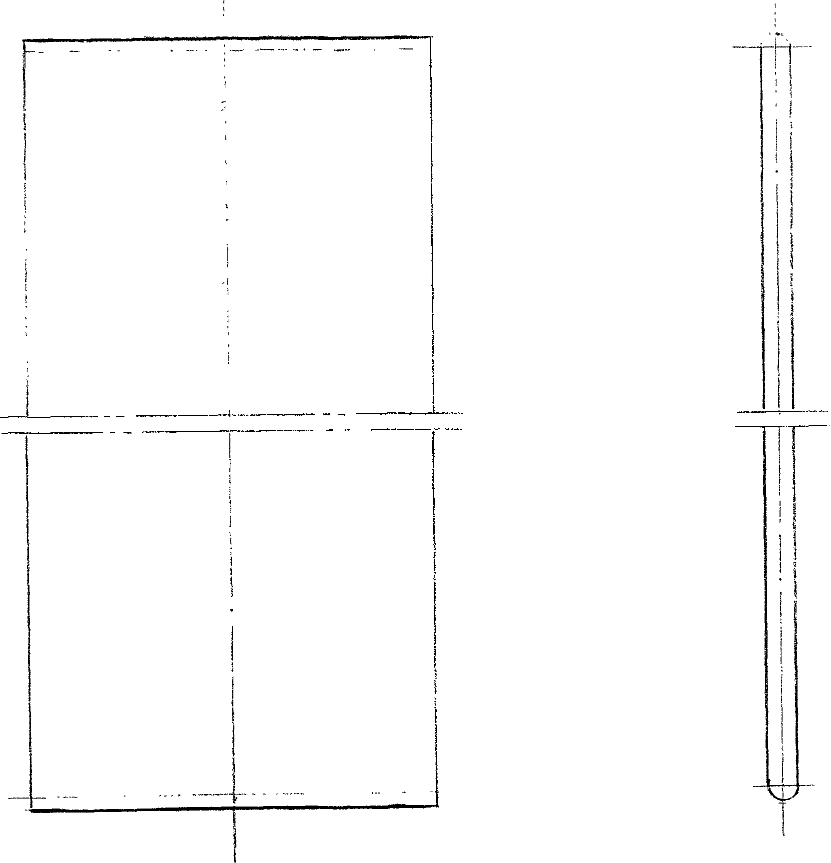
[0023] figure 1 , figure 2 Among them, in order to ensure the stability of the toggle in the swing process, the present invention widens the toggle to a plate structure. Due to the widening of the toggle, the stress surface is lengthened and the pressure intensity is reduced. In addition, at both ends of the length direction processed into a circular arc, such as figure 2 , allow it to roll on the force-bearing surface to reduce friction, so that the toggle lever (2), (3) hardly has other external force losses during the force-bearing process. Because all adopt the rolling high-paying contact, so in the process of pressing and unclamping, the relative force-bearing surfaces can not be separated, and the spring (5) is adopted to make it reset without affecting the kinematic relationship. Another positioning stop block (6) is provided to p...


PUM


Abstract

This invention relates to a press method for pneumatic toggle link cell plastic covers, which acts on the hinge joint of the upper and lower toggle links with a piston based on the theory of increasing force under the condition that the upper and lower toggle links approach to line to realize quick press and release.

Description

technical field [0001] The invention relates to a pneumatic toggle pressing method, which is suitable for the production of accessories of battery plastic covers. Background technique [0002] At present, my country's dry battery industry produces a large # When the plastic cover of the battery is used, the pressing device used is a 1.5KW motor, which is decelerated by the first-stage bridge belt, and then driven by the small pulley to drive the large flywheel for the second deceleration, and then a The cam, which presses the lower roller to transmit the pressing force, such a device consumes a lot of power, the mechanical transmission is complicated, the work efficiency is not high, and there is a large pressure on the force point, the force is not easy to balance, and the maintenance is large. The disadvantage of high maintenance costs. Contents of the invention [0003] The purpose of the present invention is to provide a simple and reliable device for pressing the ba...

Claims


Application Information

Patent Timeline
Patent Type & Authority Applications(China)
IPC IPC(8): B29D24/00B29D99/00H01M2/04
CPCY02E60/12Y02E60/10
Inventor 王贤正
Owner 王贤正
Learn More