Cutting method and cutting apparatus for layered sheet, layered sheet, optical element and image display

A technology of optical components and laminations, applied in optics, polarizing components, metal processing, etc., can solve problems such as large cracks

Active Publication Date: 2005-07-20
NITTO DENKO CORP
View PDF1 Cites 15 Cited by
  • Summary
  • Abstract
  • Description
  • Claims
  • Application Information

AI Technical Summary

Problems solved by technology

[0005] However, there is a problem that in the prior art disclosed in the following Patent Document 1, cracks along the stretching direction are large during cutting, causing problems in appearance.
In addition, in recent years, LCD panels have tended to become narrower bezels, and the requirements for the dimensional accuracy and end appearance of polarizers mounted on the panels have become more and more stringent. Under such circumstances, the following patent documents The prior art disclosed in 1 is still insufficient in processing the cutting surface into a good state with excellent precision

Method used


Image

  • Cutting method and cutting apparatus for layered sheet, layered sheet, optical element and image display
  • Cutting method and cutting apparatus for layered sheet, layered sheet, optical element and image display
  • Cutting method and cutting apparatus for layered sheet, layered sheet, optical element and image display

Examples


Embodiment approach

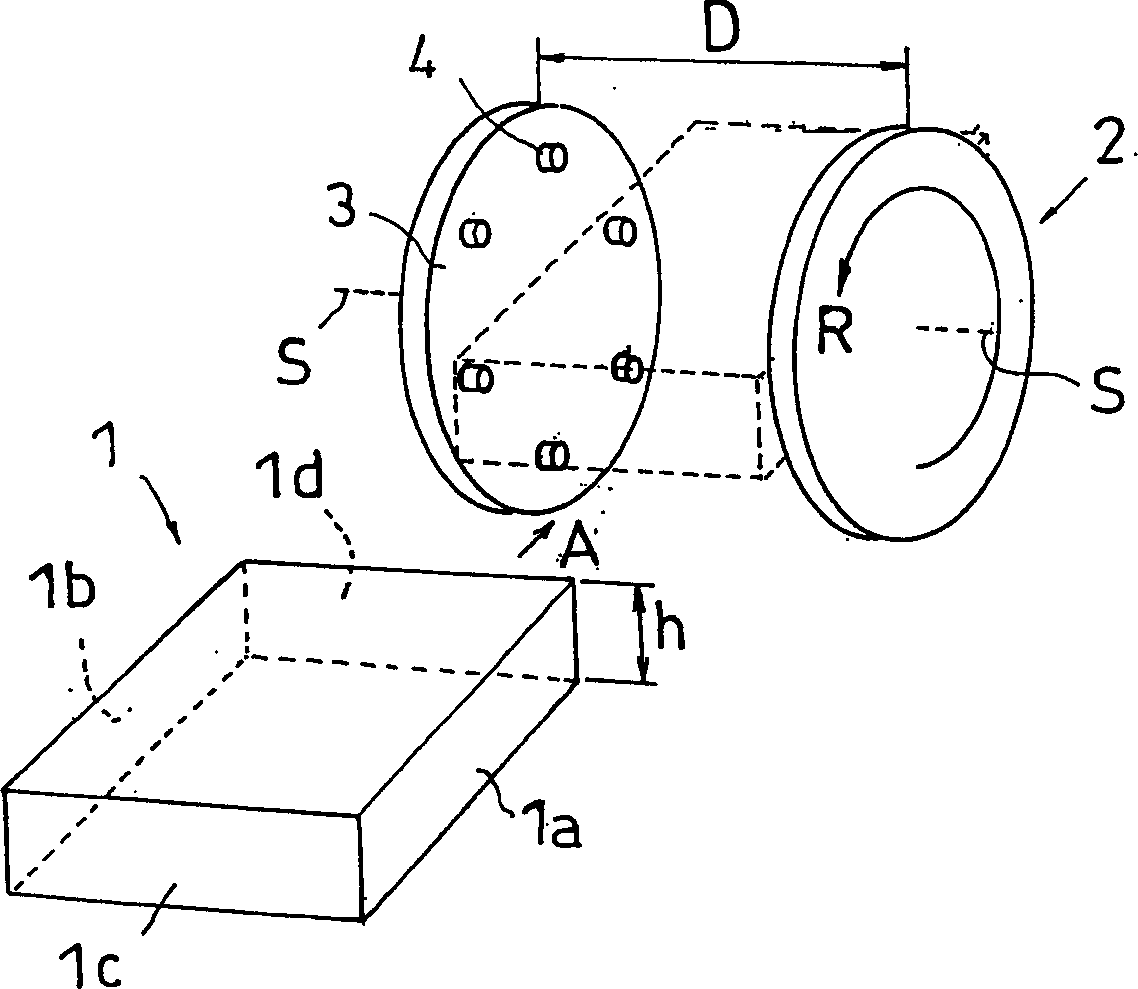
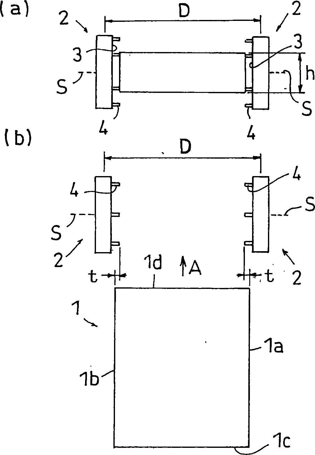
[0092] (1) In the above-mentioned embodiment, the example in which cutting is performed by moving the workpiece 1 toward the cutting member side is described, but the present invention is not limited thereto, and the cutting member 2 may be moved toward the workpiece 1. Direction movement for cutting. In addition, it is not limited to the example of carrying the workpiece 1 between a pair of cutting members 2 as shown in the above-mentioned embodiment, and it is also possible to use one cutting member 2 for processing, or use a plurality of cutting members 2 for one cutting surface. And for processing. Furthermore, the cutting member 2 can be relatively moved in a direction substantially perpendicular to the cutting surface.

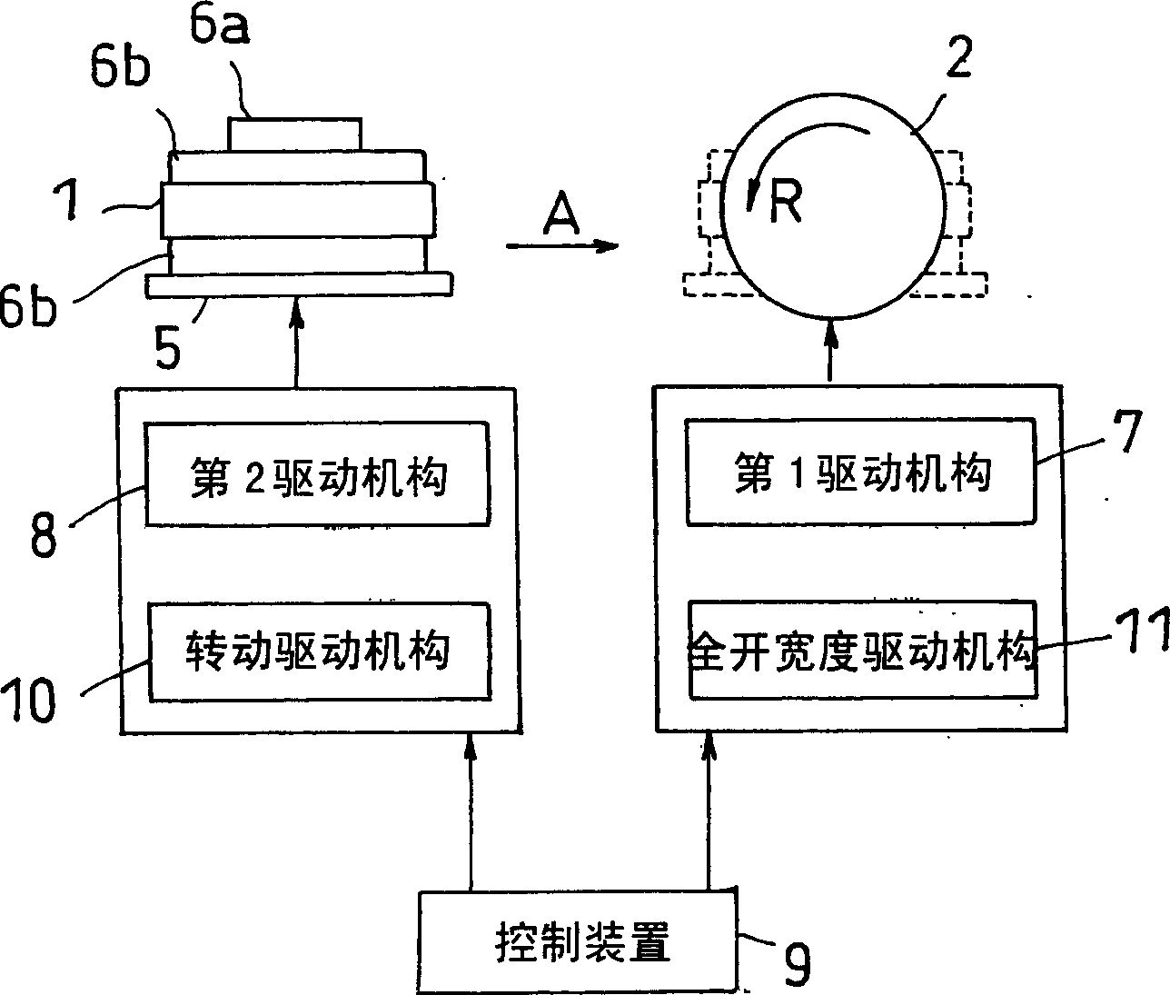
[0093] (2) In the cutting machine of the present invention, the second drive mechanism 8 may also function as the rotation drive mechanism 10, or may be provided independently. The same applies to the first drive mechanism 7 and the full-open width dri...

Embodiment 1~5

[0098] Thirty sheets of the above-mentioned polarizing plates cut to 310 mm x 235 mm were stacked in the thickness direction, and cut to 305 mm x 230 mm according to the above-mentioned embodiment. When performing the cutting process, the rotational speed of the cutting member and the moving speed of the base were set to the conditions shown in Table 1, and were used as Examples 1 to 5, respectively.


PUM

PropertyMeasurementUnit
thicknessaaaaaaaaaa

Abstract

To provide a machining method for machining a cut surface of a laminated sheet with high precision so as to have a good sectional condition and so as to resist tearing in a drawing orientation; a machining device; a laminated sheet which is machined according to the machining method; an optical member; an optical element equipped with the optical member; and an image display device having the optical member or the optical element installed therein. The machining method is provided for machining the cut surface of the laminated sheet which is cut into rectangular pieces. The method is comprised steps of: forming an object 1 to be machined by superposing the plurality of laminated sheets on each other; rotating a machining member 2 having a rotation shaft S perpendicular to the cut surfaces 1a, 1b of the object 1 to be machined, and a machining blade 4 protruding toward the cut surface of the object 1 to be machined, about the rotation shaft S; and relatively moving the object 1 to be machined, with respect to the machining member 2 such that the machining blade 4 makes a contact with the cut surfaces 1a, 1b of the object 1 to be machined.

Description

technical field [0001] The present invention relates to a cutting method and a cutting device for a laminated sheet, a laminated sheet cut by the method, an optical element including the laminated sheet, and an image display device equipped with the laminated sheet or the optical element. It is especially useful when using a polarizing plate as a laminated plate. Background technique [0002] A polarizing plate is widely used as a component of a liquid crystal display device (hereinafter, may be abbreviated as LCD), and the demand for it is rapidly increasing in recent years. In addition, the use of high-value-added polarizers with optical compensation functions and brightness improvement functions is also increasing, and the demand for display quality is also tending to increase. As a polarizing plate, a protective film such as cellulose triacetate is laminated on both sides of a polarizing film composed of an oriented polyvinyl alcohol film adsorbed with iodine or a dichr...

Claims


Application Information

Patent Timeline
Patent Type & Authority Applications(China)
IPC IPC(8): G02F1/13B23C1/00B23C3/12B23D1/00B26D1/29G02B5/30
CPCB26D1/29Y10T409/50082Y10T409/50246Y10T409/307784G02F1/13
Inventor 东尾和广本村弘则金谷实
Owner NITTO DENKO CORP
Why Eureka
Try Eureka