Connection structure of side member to cross member

A technology for connecting structures and side members, applied in the directions of upper structure, lower structure, and upper structure sub-assembly, etc., can solve the problems of increasing the weight and complexity of the structure, increasing the number and so on.

Inactive Publication Date: 2005-07-13
ISUZU MOTORS LTD
View PDF2 Cites 2 Cited by
  • Summary
  • Abstract
  • Description
  • Claims
  • Application Information

AI Technical Summary

Problems solved by technology

Therefore, the number of parts increases, resulting in increased weight and complexity of the structure

Method used


Image

  • Connection structure of side member to cross member
  • Connection structure of side member to cross member
  • Connection structure of side member to cross member

Examples


Embodiment Construction

[0028] An embodiment of the present invention will be described below with reference to the accompanying drawings.

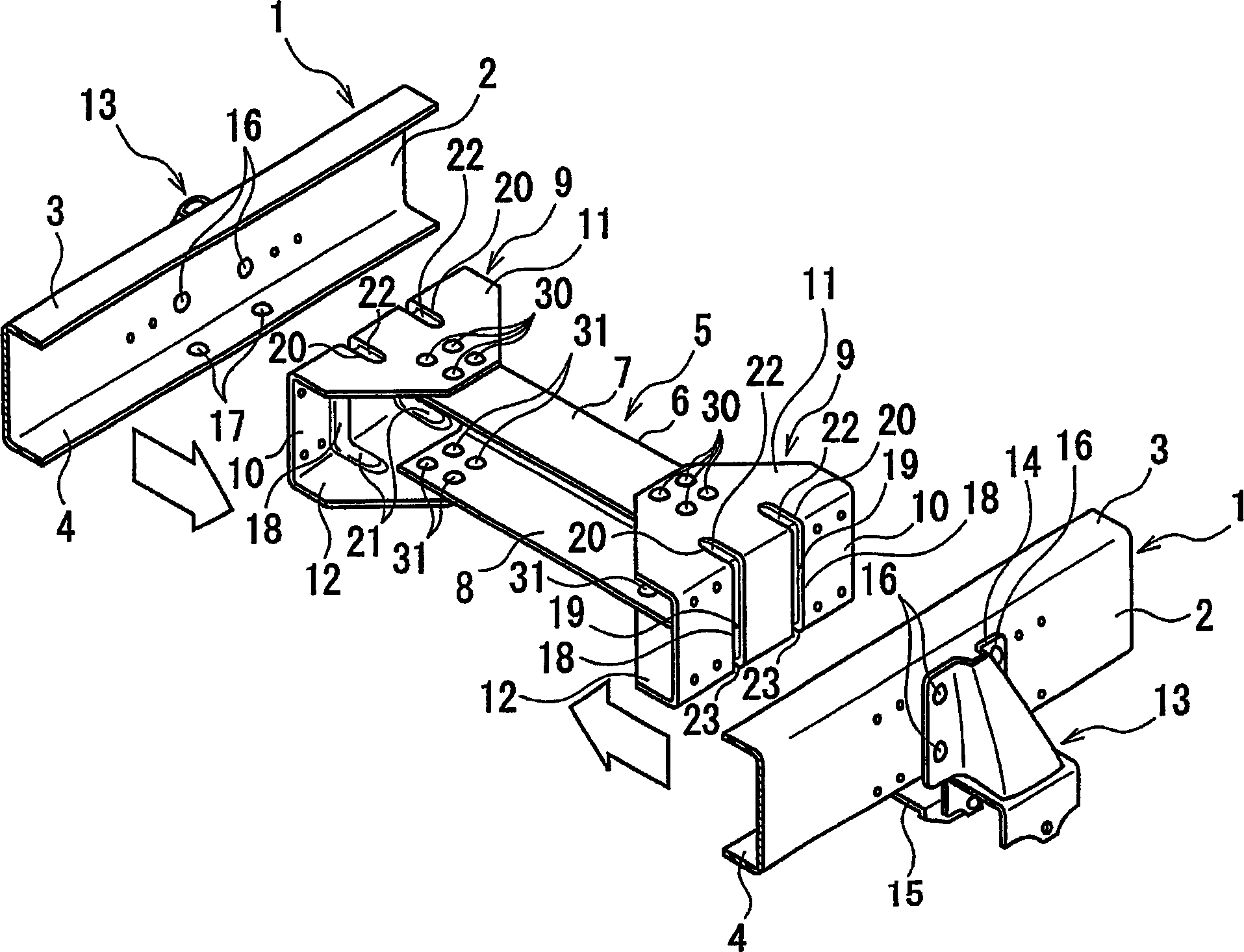
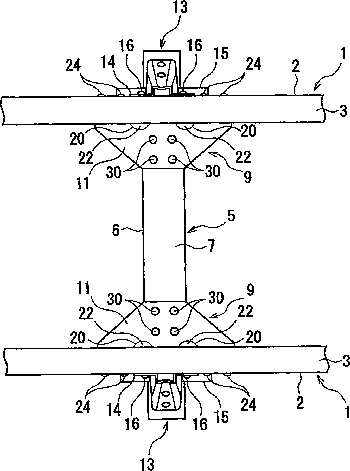
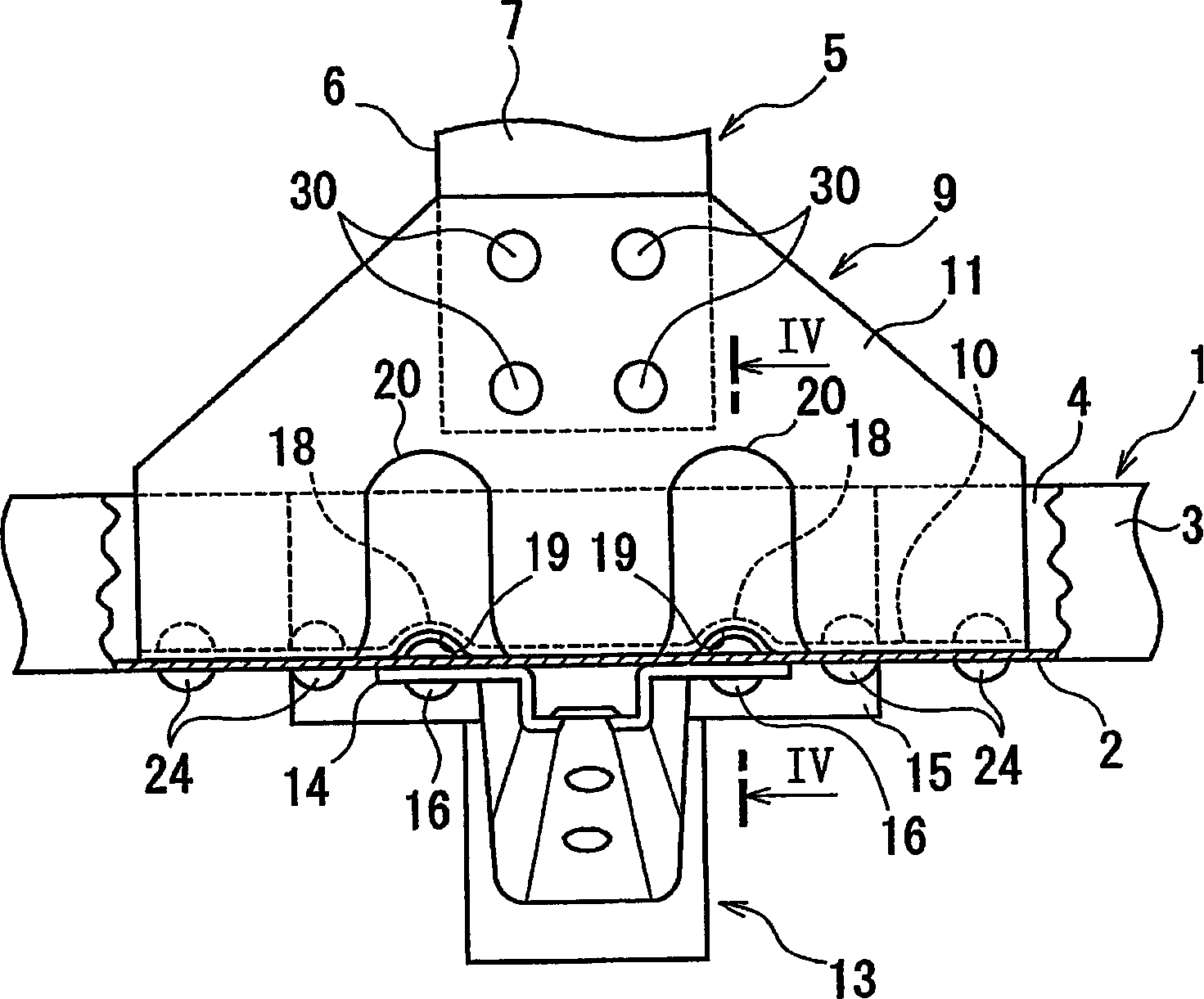
[0029] figure 1 is an exploded perspective view of the connection structure according to this embodiment. figure 2 yes figure 1 A top view of the assembled state. image 3 yes figure 2 An enlarged view of the main part with the upper horizontal plate of the side member shown partially broken. Figure 4 is along image 3 Sectional view taken along line IV-IV. Note that in the following description, the longitudinal direction refers to the front-rear direction of the vehicle body, and the lateral direction refers to the left-right direction seen when facing the front side of the vehicle body.

[0030] Such as figure 1 and 2 As shown, a pair of left and right side members 1 and a cross member 5 are provided as frame members at the lower portion of the vehicle body having a frame. The side members 1 extend in the longitudinal direction of the vehicle bod...


PUM


Abstract

A gusset connecting the lateral end of the cross bar to the side plate, comprises vertical plate and upper and lower lateral plates. Ribs formed in the vertical plate, form recesses in its lateral outer surface to fit the rivets used for fixing leaf spring bracket to lateral outer surface of vertical wall of side plate, so as to fix the vertical plate to the lateral inner surface of the vertical wall in surface contact state.

Description

technical field [0001] The present invention relates to a connection structure between a side member and a cross member in a frame of a vehicle body. Background technique [0002] There is known a connection structure in the past, which utilizes a gusset plate to connect side members arranged longitudinally along the vehicle body to cross members arranged laterally along the vehicle body (as prior art, please refer to Japanese Patent Laid-Open No. 5-58569 and 4- Bulletin No. 51871). [0003] For example, if Figure 5A and 5B As shown, one side member 101 has a generally U-shaped cross-section formed by a vertical wall 102 and upper and lower horizontal walls 103 and 104 . The upper and lower horizontal walls 103 and 104 are respectively bent from the upper and lower ends of the vertical wall 102, and extend toward the vehicle body laterally inner side. One cross member 105 has a substantially U-shaped cross section constituted by side walls 106 , upper walls 107 and lower...

Claims


Application Information

Patent Timeline
Patent Type & Authority Applications(China)
IPC IPC(8): B62D25/20B62D21/02
CPCB62D21/02
Inventor 伊藤淳松本文隆齐藤政信佐藤浩至
Owner ISUZU MOTORS LTD
Why Eureka
Try Eureka