Trans mitter-receiver
A technology of sending, receiving and sending calls, which is applied in the direction of telephone communication, side tone elimination circuit, electrical components, etc., and can solve the problems of lowering of the sending signal level and ineffective side tone control function, etc.
- Summary
- Abstract
- Description
- Claims
- Application Information
AI Technical Summary
Problems solved by technology
Method used
Image
Examples
no. 1 example
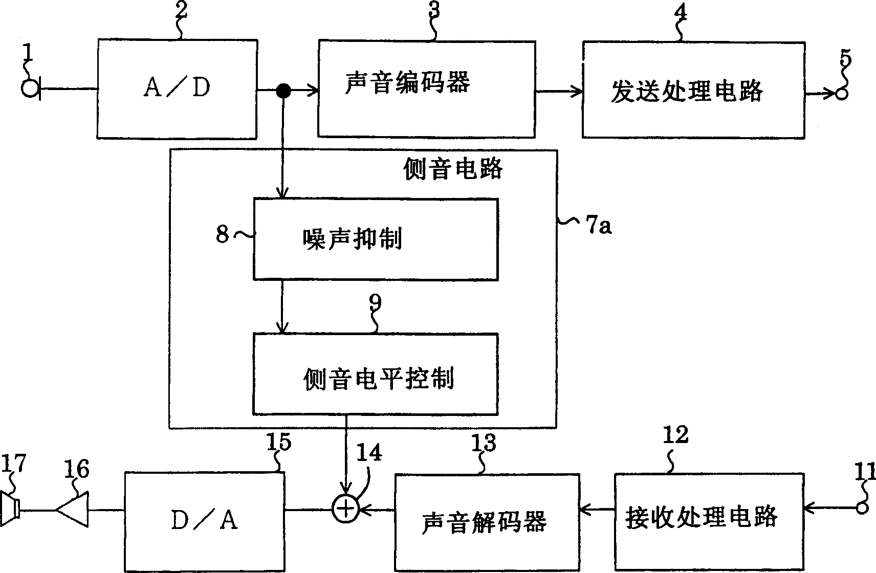
[0043] figure 1 It is a block diagram for explaining the brief configuration of the telephone receiver with sidetone circuit according to the first embodiment of the present invention. This transmitting and receiving device includes a transmitting microphone 1 that collects the voice of the user (speaker) to generate a transmitting signal, and an A / D that converts the transmitting signal generated by the transmitting microphone 1 from an analog signal to a digital signal. A converter 2, a voice encoder 3 for encoding and compressing the speech signal converted into a digital signal by the A / D converter 2, and a transmission processing circuit for performing signal processing for transmission on the coded signal compressed by the voice encoder 3 4. Use the output terminal 5 for transmitting the transmission signal generated by the transmission processing circuit 4 through the telephone line or antenna, etc., suppress the background noise contained in the transmission signal co...
no. 2 example
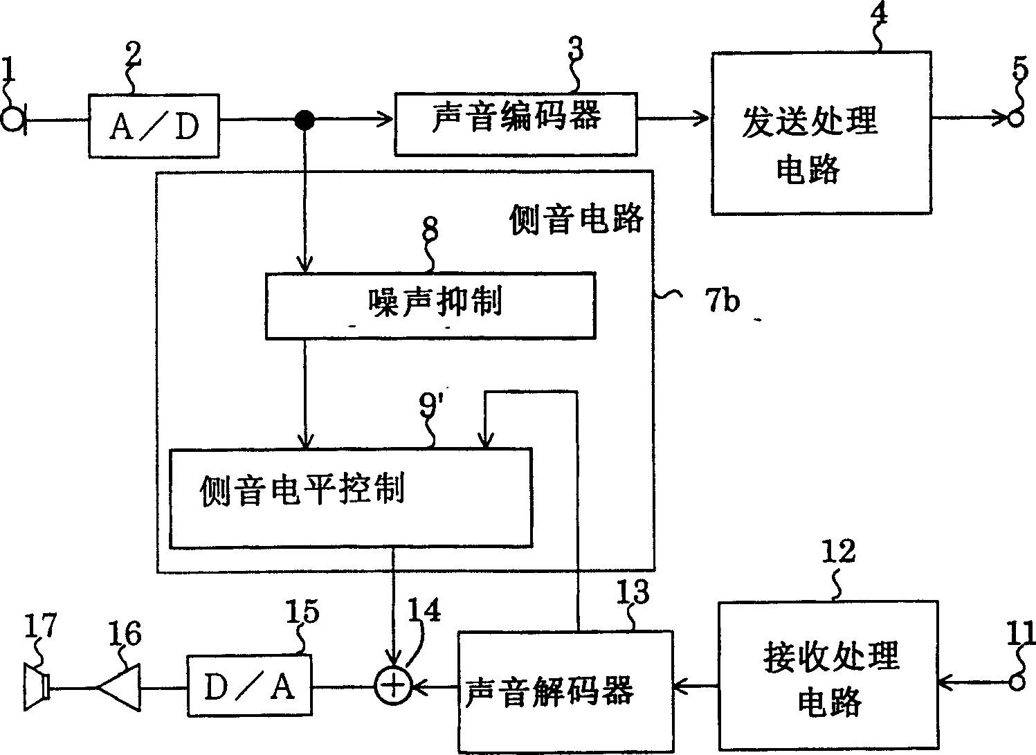
[0055] figure 2 Shown is a brief structural block diagram of the telephone sending and receiving device according to the second embodiment of the present invention. The sending and receiving phone device of the present embodiment and figure 1 Compared with the speaking device of the first embodiment shown, the only difference is that the side tone level controller controls the level of the side tone according to the level of the speaking signal and the level of the receiving signal. Therefore, detailed descriptions of redundant configurations and functions will not be repeated. In addition, the reference numerals of the sidetone circuit and the sidetone level controller of this embodiment are described with 7b and 9' respectively.
[0056] The side tone circuit 7b includes a noise suppressor 8 that suppresses the background noise contained in the speech signal that is converted into a digital signal output by the A / D converter 2; 1. A side tone level controller 9 ′ for co...
no. 3 example
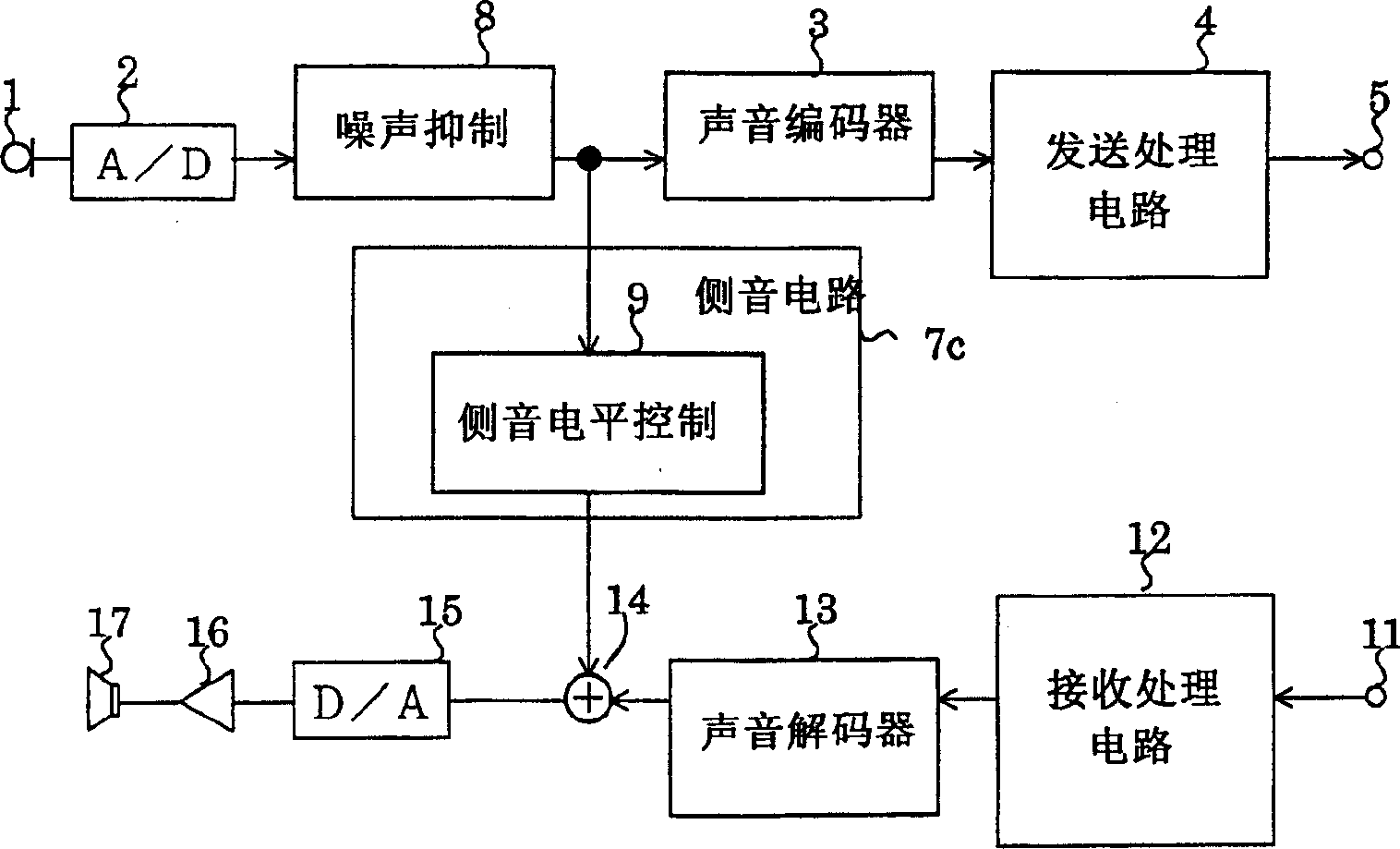
[0061] image 3 Shown is a brief structural block diagram of the telephone sending and receiving device according to the third embodiment of the present invention. The sending and receiving phone device of the embodiment and figure 1 Compared with the telephone receiver of the first embodiment shown, the only difference is that the noise suppressor 8 included in the sidetone circuit 7a is connected between the A / D converter 2 and the voice coder 3. Therefore, detailed descriptions of redundant configurations and functions will not be repeated. In addition, the reference numeral of the sidetone circuit in this embodiment is described with 7c.
[0062] The voice encoder 3 compresses and encodes the speech signal whose background noise has been suppressed by the noise suppressor 8 , and outputs it to the transmission processing circuit 4 .
[0063] The sidetone circuit 7c includes a sidetone level controller 9 that controls the level of the speech signal after background nois...
PUM
 Abstract
Description
Claims
Application Information
 - R&D
- Intellectual Property
- Life Sciences
- Materials
- Tech Scout
- Unparalleled Data Quality
- Higher Quality Content
- 60% Fewer Hallucinations
Browse by: Latest US Patents, China's latest patents, Technical Efficacy Thesaurus, Application Domain, Technology Topic, Popular Technical Reports.
© 2025 PatSnap. All rights reserved.Legal|Privacy policy|Modern Slavery Act Transparency Statement|Sitemap|About US| Contact US: help@patsnap.com


