
Shock absorber with frequency-dependent damping

A shock absorber and flow resistance technology, applied in shock absorbers, springs/shock absorbers, shock absorbers, etc., can solve problems such as narrow passages

Inactive Publication Date: 2005-06-15
科尼公司
View PDF2 Cites 13 Cited by
  • Summary
  • Abstract
  • Description
  • Claims
  • Application Information

AI Technical Summary

Problems solved by technology

[0005] In U.S. Patent 5 392 833 there is described a device comprising an auxiliary chamber with an opening in the chamber with a valve under slight elastic pressure acting in one direction, the valve also having an opening, but , this opening has a narrower passage

Method used


Image

  • Shock absorber with frequency-dependent damping
  • Shock absorber with frequency-dependent damping
  • Shock absorber with frequency-dependent damping

Examples


Embodiment Construction

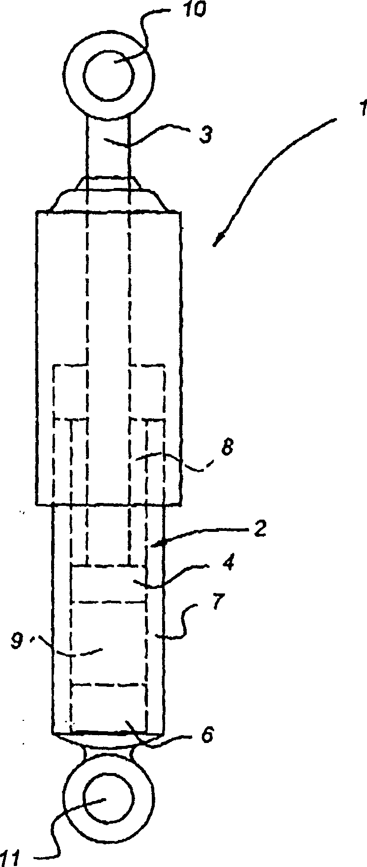
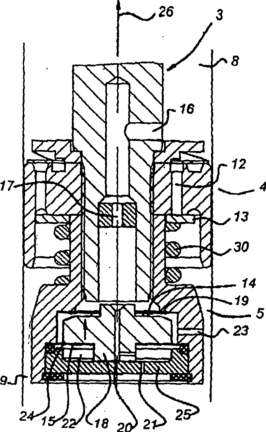
[0033] figure 1 , the shock absorber is generally indicated by reference numeral 1 . The shock absorber comprises a cylinder part 2 and a piston part 3 . The piston part 3 contains a piston 4 which delimits two oppositely positioned cavities within the cylinder part. Reference numeral 8 designates a first cavity and reference numeral 9 designates a second cavity. Via the eyelet 10, the piston part 3 can be fixed, for example, to the fuselage of a vehicle. Eyelets 11 are used, for example, for fastening to a part of a suspension system of a vehicle. The shock absorber shown here is of the type in which the cylinder part 2 contains an annular channel 7 for storing shock absorber fluid and also has a bottom valve 6 connecting the second chamber 9 to the fluid storage chamber 7 . It should be understood that the present invention can be applied to any type of shock absorber, with or without an external reservoir, which can be made in some manner known in the art.

[0034] The...


PUM


Abstract

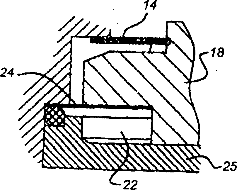
The shock absorber includes a flow channel (16) with a valve device and made in the piston part. The valve unit is designed to be hydraulically actuated. For this purpose, there is an auxiliary chamber (22, 42), one side of which is closed by a mobile valve body (18). The valve body has an inlet that allows oil to flow from the passage into the auxiliary chamber. There is also an exit (21, 41) (the exit can be closed). The surface area of ​​the valve body acting on the valve seat (19) is less than the surface area of ​​the valve body in the auxiliary cavity. In this way, the liquid flowing through the valve body inlet causes an increase in the volume of the auxiliary cavity and causes the closing action of the valve body. Since it takes some time to fill the auxiliary cavity, the frequency-dependent closing properties of the flow channel are obtained.

Description

technical field [0001] The present invention relates to a shock absorber comprising a cylinder portion and a piston portion movable in the cylinder. The piston part and the cylinder part each have a joint for connecting mutually movable elements to each other, and said piston part and said cylinder part are sealed so as to define cavities on either side of them, a first cavity abutting said piston part joints, the second cavity abuts the joints of the cylinder part. There is a connecting channel between the cavities for connecting the cavities. Said connecting channel comprises valve means for changing the fluid flow through said connecting channel, said valve means comprises a valve seat and an element which can move relative to the valve seat under fluid pressure and valve seat sealing state, said valve means The moving element forms a boundary wall of an auxiliary chamber having an inlet opening in an upstream direction of the valve device as viewed in the direction of fl...

Claims


Application Information

Patent Timeline
Patent Type & Authority Applications(China)
IPC IPC(8): F16F9/46F16F9/512
CPCF16F9/512F16F2228/04Y10T137/88054
Inventor 保罗·德科克安德里阿努斯·安东尼厄斯·威廉默斯·德勒伊特
Owner 科尼公司
Learn More