
Voltage virtual value measuring method based on filter

A voltage effective value and measurement method technology, applied in the direction of effective value measurement, etc., can solve the problems of poor real-time performance, poor stability, large error jump table, etc., and achieve the effect of simple structure, high precision, and simplified complicated work

Inactive Publication Date: 2005-04-20
HI TREND TECH SHANGHAI
View PDF0 Cites 16 Cited by
  • Summary
  • Abstract
  • Description
  • Claims
  • Application Information

AI Technical Summary

Problems solved by technology

The biggest weakness of this measurement method is poor real-time performance, insufficient precision, large error jump table and poor stability

Method used


Image

  • Voltage virtual value measuring method based on filter
  • Voltage virtual value measuring method based on filter
  • Voltage virtual value measuring method based on filter

Examples


Embodiment Construction

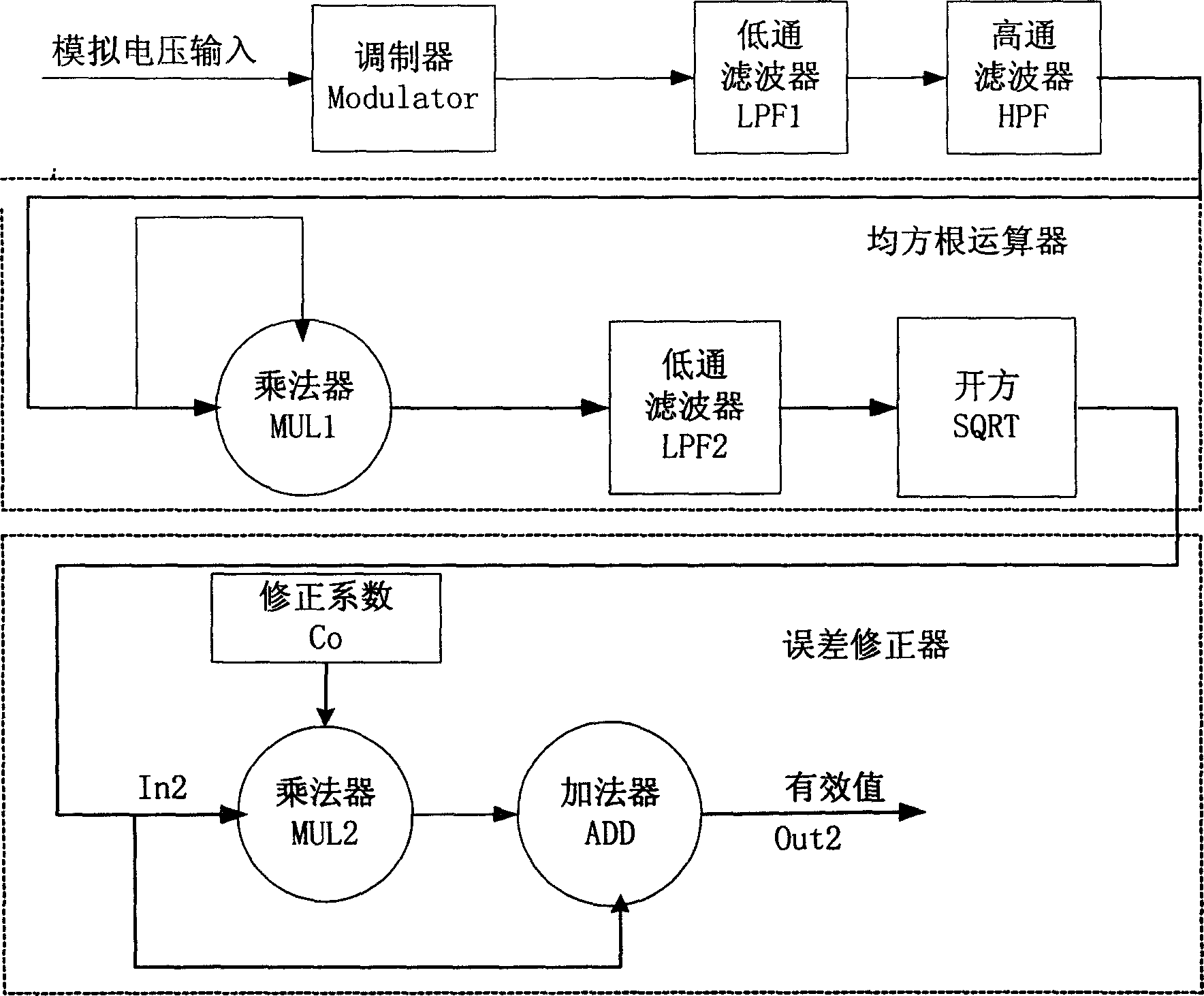
[0017] For the measurement of the effective value of the voltage in the multi-functional electric energy meter, the sampling voltage is sampled by a sigma-delta modulator to obtain a one-bit data stream close to 1MHz. After a low-pass filter using a comb filter structure, the The one-bit high-speed data stream output by the modulator is down-frequency processed and converted into a low-speed multi-bit data stream. Anti-aliasing filtering is performed while down-frequency. Since only pure AC signals are considered, a digital high-pass filter is used to reduce The low-speed data stream after the frequency is subjected to DC blocking processing. After the data after DC blocking is passed through the root mean square operator composed of a multiplier, a digital filter and a square extractor, the effective value of the voltage is obtained, and finally the error of the obtained effective value of the voltage is corrected by an error corrector.


PUM


Abstract

A method for testing effective voltage value by a filter includes signal sample conditioning, a mean-square-root operation unit and an error corrector, among which, the signal sample conditioning contains a modulator, a LPF1 and a digital HPF, the mean-square-root operation unit is composed of a MUL1, a LPF2 and a SQRT, the error corrector coefficient register. The signal sample conditioning finishes signal sampling accurately, the mean-square-root operation unit finishes computation of voltage effective value according to the data input by sample conditioning and the error corrector corrects the error of the voltage effective value.

Description

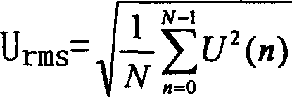
Technical field [0001] The invention relates to a method for measuring the effective value of voltage by using a filter. Background technique [0002] The traditional method of measuring the effective value of voltage based on sampling theory is to obtain the root mean square calculation of the sampling points within a certain period. According to circuit theory, the effective value of voltage is defined as U rms = 1 T ∫ 0 T u 2 ( t ) dt , The sampling calculation method is used to measure the effective value of the voltage. The theoretical basis is the sampling theorem. Under the premise of satisfying the sampling theorem, the measured signal voltage u(t) i...

Claims


Application Information

Patent Timeline
Patent Type & Authority Applications(China)
IPC IPC(8): G01R19/02
Inventor 邹建发
Owner HI TREND TECH SHANGHAI
Learn More