


Quick Research
Generate reliable direction feasibility study reports for your R&D in just a few steps.

Technical Q&A
Discover and master advanced knowledge NOW. Basics, ideas, possibilities, all at once.

Find Solutions
As an expert in R&D theories, this can generate solutions to your technical problems instantly.

Evaluate Feasibility
Analyze your overall solution with one click, know your potential R&D risks in advance.

Monitor Landscape
Get weekly tech updates, stay abreast of the latest tech innovations and key insights.
Reflector and liquid crystal display device using the same
A technology of reflectors and recesses, which is applied in the direction of diffusion elements, static indicators, optics, etc., can solve the problems of reduced reflectivity, darkened display, etc., and achieve the goal of expanding the range of viewing angles, expanding the characteristics of viewing angles, and improving visual resolution Effect
- Summary
- Abstract
- Description
- Claims
- Application Information
AI Technical Summary
Problems solved by technology
Method used
Image

Examples
no. 1 Embodiment approach
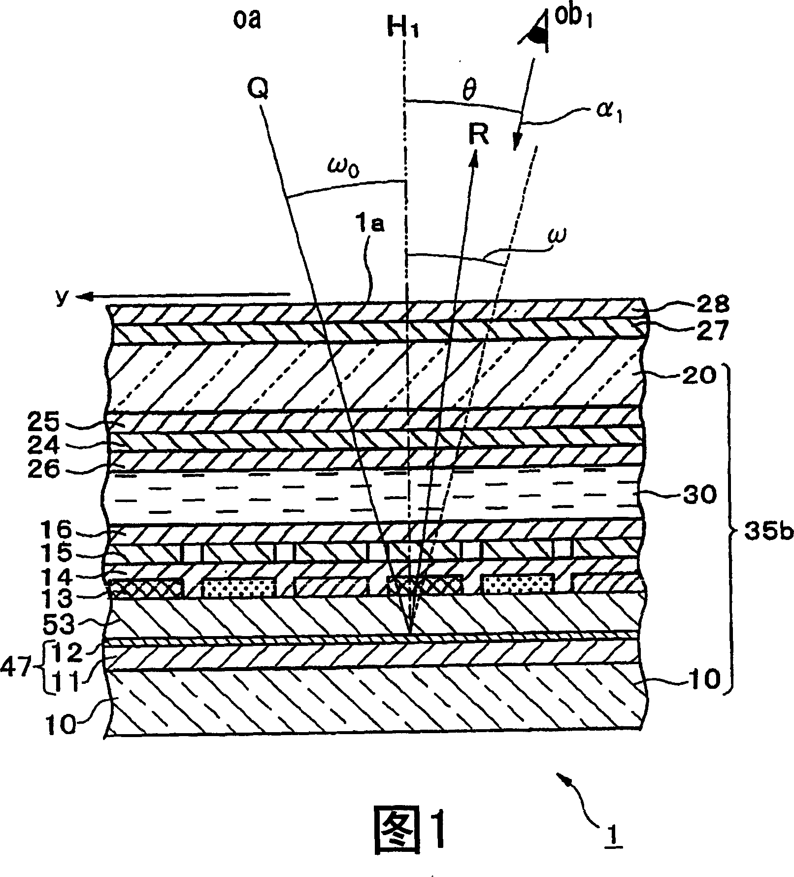
[0058] FIG. 1 is a schematic partial cross-sectional structural view schematically showing a simple matrix reflective liquid crystal display device according to a first embodiment of the present invention.
[0059] In FIG. 1 , the reflective liquid crystal display device 1 has a structure in which a first substrate 10 (the other substrate away from the viewing side) and a second substrate 20 are formed of opposing transparent glass with a liquid crystal layer 30 sandwiched between them. (The substrate on the observation side) is bonded together by a sealing material (not shown) provided annularly at the edge of the two substrates 10 , 20 .
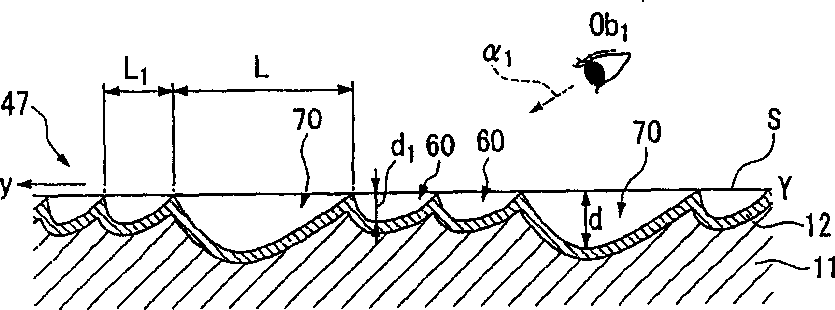
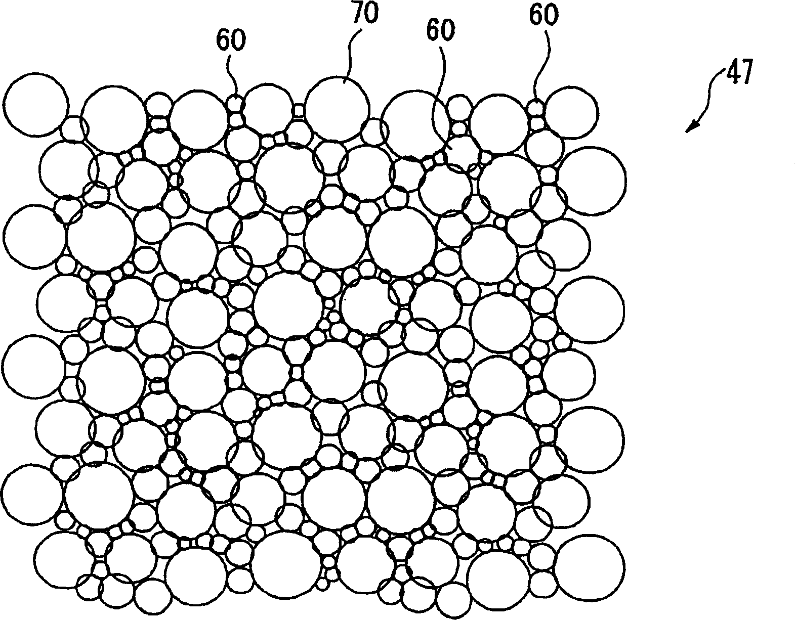
[0060] On the inner surface side (the liquid crystal layer 30 side) of the first substrate 10, a reflector 47, a transparent interlayer 53 formed as desired, a color filter 13 for color display, and a color filter 13 for color display are sequentially stacked and formed. A protective film (overcoat film) (transparent planarization layer) 1...
no. 2 Embodiment approach
[0115] Next, a reflection type liquid crystal display device as a second embodiment of the present invention will be described.
[0116] 13 is a schematic diagram showing a partial cross-sectional structure of a reflective liquid crystal display device according to a second embodiment.
[0117] Reflective liquid crystal display device 100 of the second embodiment and FIGS. image 3 The first reflective liquid crystal display device 1 shown differs in the structure of the reflector provided in the liquid crystal cell, and in the outer surface of the substrate 20 which is the viewing side of the pair of substrates 10 and 20 constituting the liquid crystal cell. A light scattering layer 29 is provided.
[0118] The reflector 47a included in the reflective liquid crystal display device 100 according to this embodiment is composed of an organic film 11a and a metal reflective film (metal film) 12a formed on the organic film 11a.
[0119] Figure 11 It is a top view showing a par...
PUM
| Property | Measurement | Unit |
|---|---|---|
| diameter | aaaaa | aaaaa |
| thickness | aaaaa | aaaaa |
| particle diameter | aaaaa | aaaaa |
Abstract
Description
Claims
Application Information
 - R&D Engineer
- R&D Manager
- IP Professional
- Industry Leading Data Capabilities
- Powerful AI technology
- Patent DNA Extraction
Browse by: Latest US Patents, China's latest patents, Technical Efficacy Thesaurus, Application Domain, Technology Topic, Popular Technical Reports.
© 2024 PatSnap. All rights reserved.Legal|Privacy policy|Modern Slavery Act Transparency Statement|Sitemap|About US| Contact US: help@patsnap.com