
Method for producing a part with a coil and electric machine comprising such a part

A manufacturing method and coil technology, which is applied in the manufacture of motor generators, electrical components, electromechanical devices, etc., can solve the problem of low filling coefficient of coils, and achieve low material cost, high filling coefficient of winding wire, and small stop The effect of torque

Inactive Publication Date: 2005-02-23
ROBERT BOSCH GMBH
View PDF0 Cites 2 Cited by
  • Summary
  • Abstract
  • Description
  • Claims
  • Application Information

AI Technical Summary

Problems solved by technology

However, this has the disadvantage that, in particular in the edge region close to the stator base body or close to the stator teeth, gaps remain which cannot be filled with wire, with the result that the coil does not have a high wire filling factor

Method used


Image

  • Method for producing a part with a coil and electric machine comprising such a part
  • Method for producing a part with a coil and electric machine comprising such a part
  • Method for producing a part with a coil and electric machine comprising such a part

Examples


Embodiment Construction

[0018] Below, refer to figure 1 - Figure 5 to illustrate the method of manufacture of an electric machine with improved coil windings proposed by the invention.

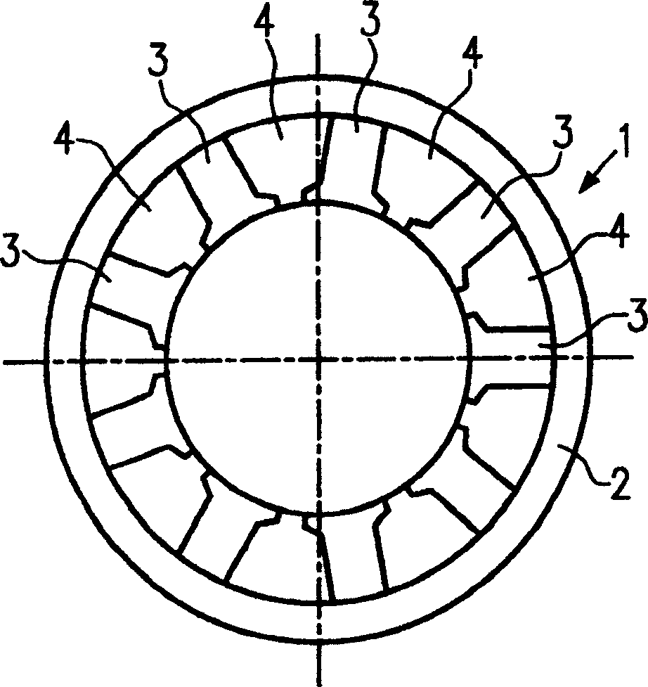
[0019] figure 1 The stator 1 of the electric machine is shown, here the stator 1 has a surrounding ring 2 and a plurality of stator teeth 3 . Such as figure 2 As shown in detail, the stator teeth are T-shaped in cross-section and have tangentially extending projections 5 , 6 at their inwardly facing end 2 , also called tooth feet.

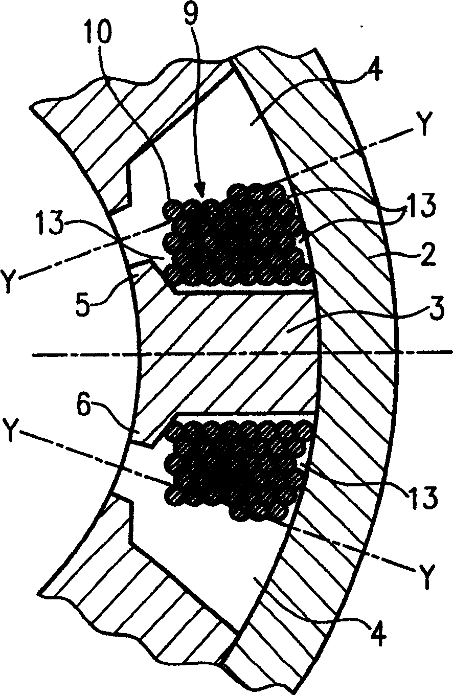
[0020] figure 2 A schematic sectional front view of the stator is shown, here a coil 9 is shown around the stator teeth 3 , which has a plurality of windings 10 made of at least one type of wire. To see it more clearly, in figure 2 - Only one coil is shown exactly in each case in FIG. 5 . The coil 9 is wound on the stator tooth 3 by a known method, for example. Such as figure 2 It is clearly shown that, due to the geometrical conditions and the winding method, some gaps 13 are...


PUM


Abstract

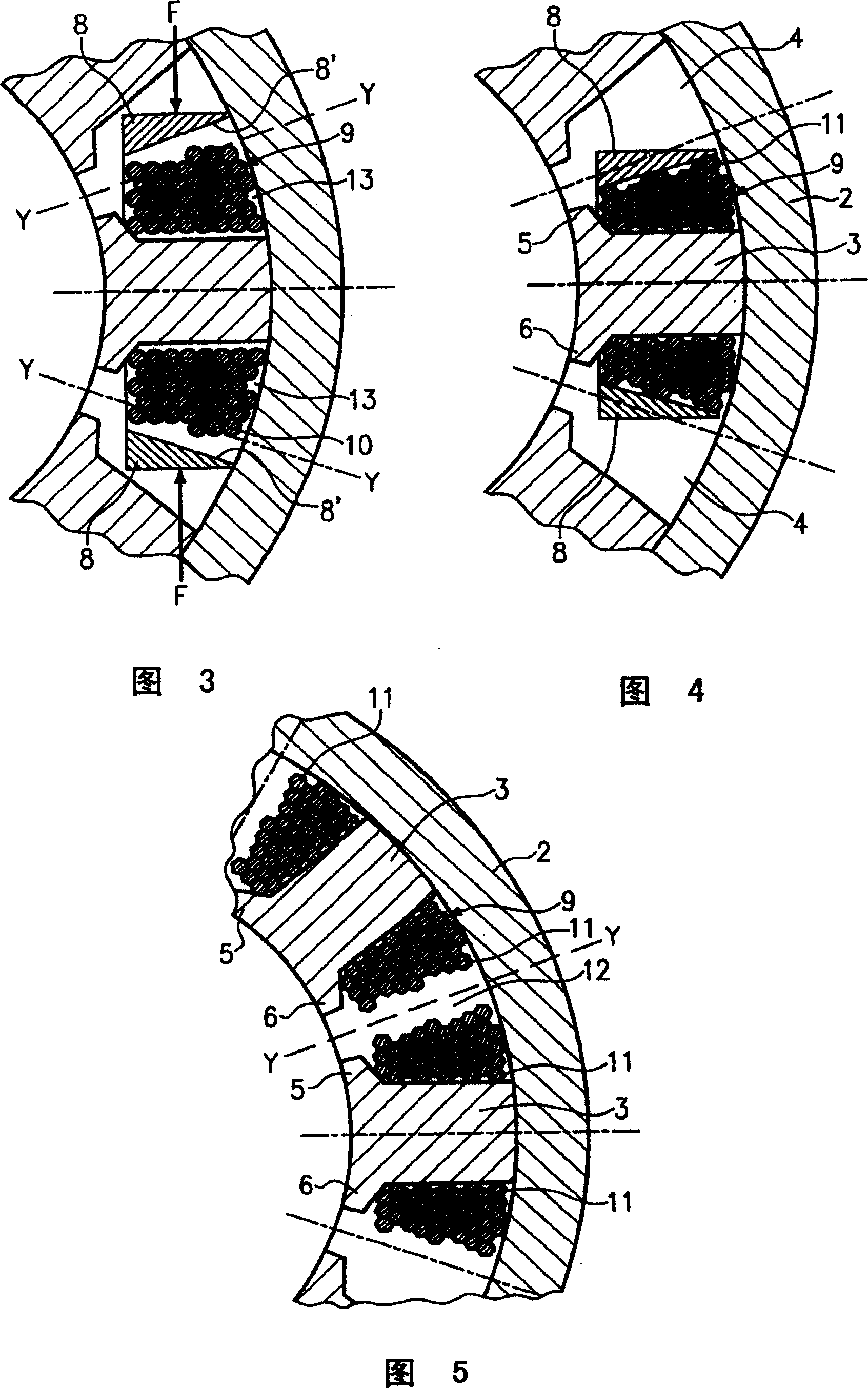
The invention relates to a method for producing a part (1) of a motor with a coil (9) comprising following steps: winding one or more wires (10) to a coil (9), whereby the wire is a baked lacquer wire with an electrically conducting core, an insulating coating and an external baked coating; pressing the wound coil with a pressing tool (8) and baking the pressed coil (9) to fix the geometric shape of the coil.

Description

technical field [0001] The invention relates to a method for producing a coiled component of an electric machine and an electric machine with the component produced in this way. Background technique [0002] Various forms of electric machines are known as electric motors or generators. For example, brushless EC motors, which have a stator as one component, have also been widely used in recent years. The role of the stator here is to conduct current. Here, the stator has a plurality of stator teeth on which a plurality of wires are wound to form a coil. In this case there are different ways of winding the coils on the stator. The winding method can be, for example, a so-called fly winding method or a needle winding method. However, this has the disadvantage that, in particular in the edge region close to the stator base body or close to the stator teeth, gaps remain which cannot be filled with wire, with the result that the coil fill factor is not high. Contents of the ...

Claims


Application Information

Patent Timeline
Patent Type & Authority Applications(China)
IPC IPC(8): H02K15/095H02K15/12
CPCH02K15/12H02K15/095
Inventor G·茨雷尔J·赫尔普C·盖达H·斯庞纳
Owner ROBERT BOSCH GMBH
Learn More