
Selective iron weighing block

A counterweight and shell technology, which is applied to heavy objects, dumbbells, etc., can solve the problems of short service life, loud motion noise, and labor-intensive work, and achieve the effects of low cost, low motion noise, and high efficiency

Inactive Publication Date: 2005-02-23
王廷琳
View PDF0 Cites 6 Cited by
  • Summary
  • Abstract
  • Description
  • Claims
  • Application Information

AI Technical Summary

Problems solved by technology

This kind of iron counterweight needs to be formed through complex processes such as turning, milling, grinding, and grinding in the production process, which is laborious, high cost, loud in motion, easy to break, and short in service life.

Method used


Image

  • Selective iron weighing block
  • Selective iron weighing block
  • Selective iron weighing block

Examples


Embodiment Construction

[0020] Below in conjunction with accompanying drawing, embodiment of the present invention is described in detail:

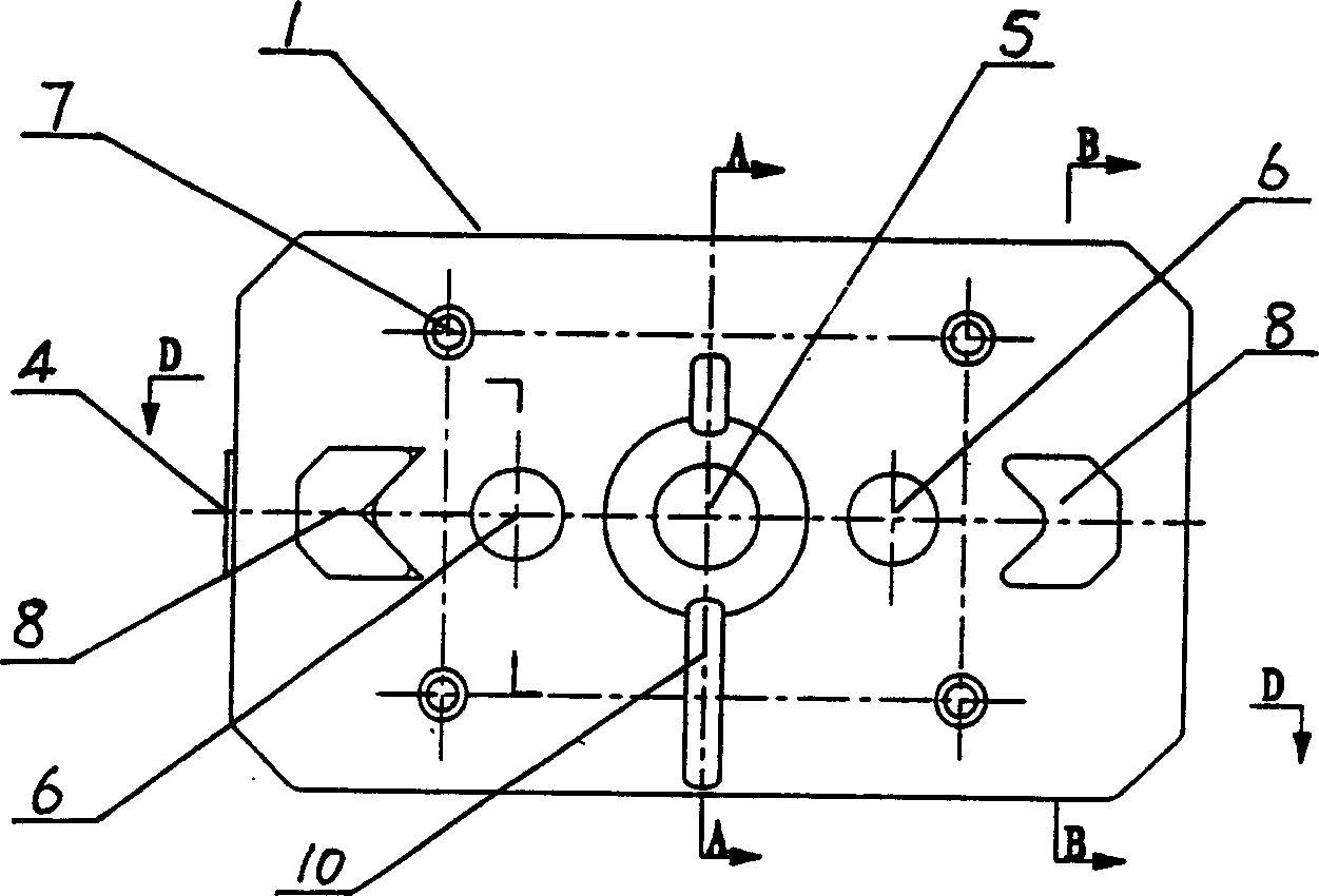
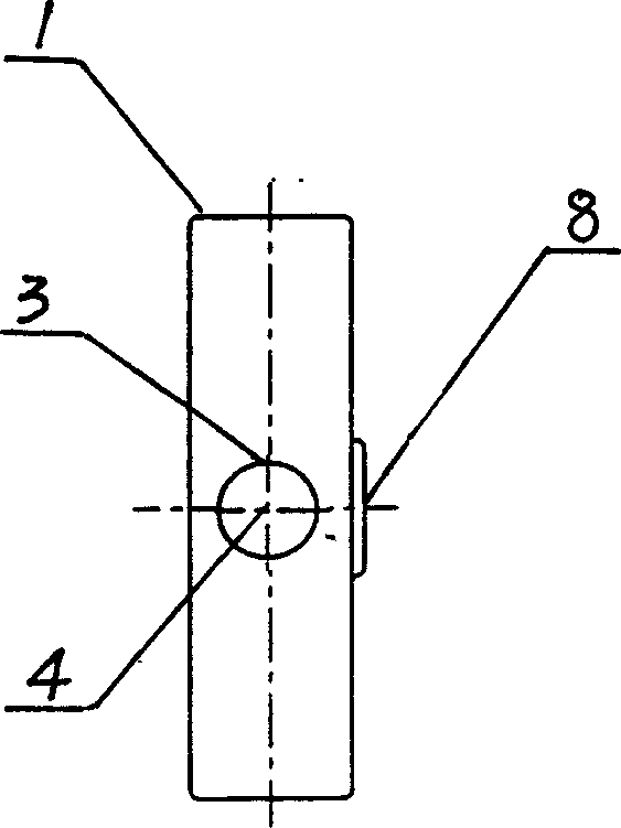
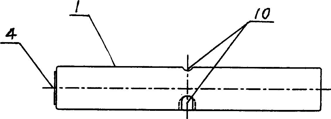
[0021] Reference attached Figure 1-7 , In the embodiment of the present invention, it includes a shell 1 and a filler 2; the shell 1 is set as an octagonal box containing a cavity, and the outer surface of the box is provided with a filling hole 3 and a closing plug 4 , the filler 2 is injected and solidified in the cavity of the shell 1 through the filling hole 3, and the closing plug 4 closes the filling hole 3; the end surface of the box is provided with a mounting hole 5, a positioning hole 6, a reinforcing rib 7, and a positioning bump 8 , positioning groove 9, latch groove 10; mounting hole 5 and positioning hole 6 are sliding through holes, and four reinforcing ribs 7 are inserted into the cavity of shell 1 to support the end face of the connecting box; one port of mounting hole 5 is set as a horn Two positioning protrusions 8 are symmetrically arranged...


PUM


Abstract

A selective counterweight for sports apparatus is composed of a plastic casing with filling hole and its plug, intalling hole, locating hole, reinforcing ribs, and locating boss and recess, and the filler which is the mixture of water, cement and sand or steel sand and can be filled in said plastic casing via said filling hole.

Description

technical field [0001] The invention belongs to sports equipment accessories, in particular to a selection iron counterweight. Background technique [0002] At present, in the common sports equipment, the iron counterweights are selected to be matched with traditional iron counterweights. This kind of iron counterweight needs to be shaped by complex processes such as turning, milling, grinding, and grinding during the production process, which is laborious, expensive, loud in motion, easy to break, and has a short service life. Contents of the invention [0003] The object of the present invention is to provide a selective iron counterweight that is easy to manufacture, saves labor and effort, is low in cost, has low motion noise, is not easy to break, and has a long service life. [0004] The invention includes a casing and a filler; the casing is set as a polygonal box with a cavity inside, and a filling hole and a closing...

Claims


Application Information

Patent Timeline
Patent Type & Authority Applications(China)
IPC IPC(8): A63B21/075
Inventor 王廷琳
Owner 王廷琳
Learn More