
Vehicle body assembling method

An assembly method and vehicle body technology, applied to motor vehicles, auxiliary devices, vehicle parts, etc., can solve problems such as spending a lot of time and effort, and reducing positioning accuracy

Inactive Publication Date: 2005-02-16
DAIHATSU MOTOR CO LTD
View PDF0 Cites 16 Cited by
  • Summary
  • Abstract
  • Description
  • Claims
  • Application Information

AI Technical Summary

Problems solved by technology

When uneven contact occurs between the roof and the left and right side parts, the positioning accuracy between the roof and the left and right side parts will be slightly reduced
[0011] The above problems can be detected, corrected and tuned during prototyping, but it takes a lot of time and effort to analyze the source of the problem

Method used


Image

  • Vehicle body assembling method
  • Vehicle body assembling method
  • Vehicle body assembling method

Examples


Embodiment Construction

[0065] In order to make the above and other objects, features, and advantages of the present invention more comprehensible, a preferred embodiment is specifically cited below, together with the accompanying drawings, and is described in detail as follows:

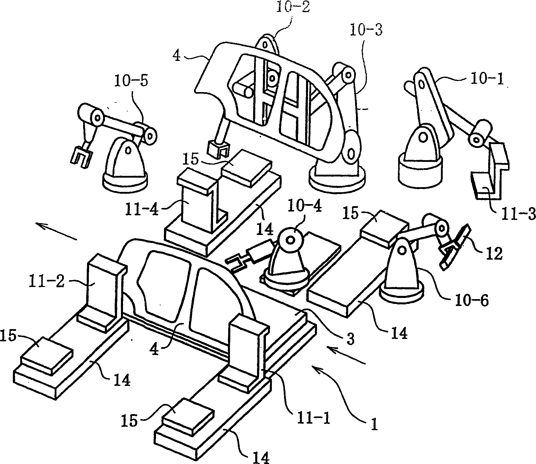
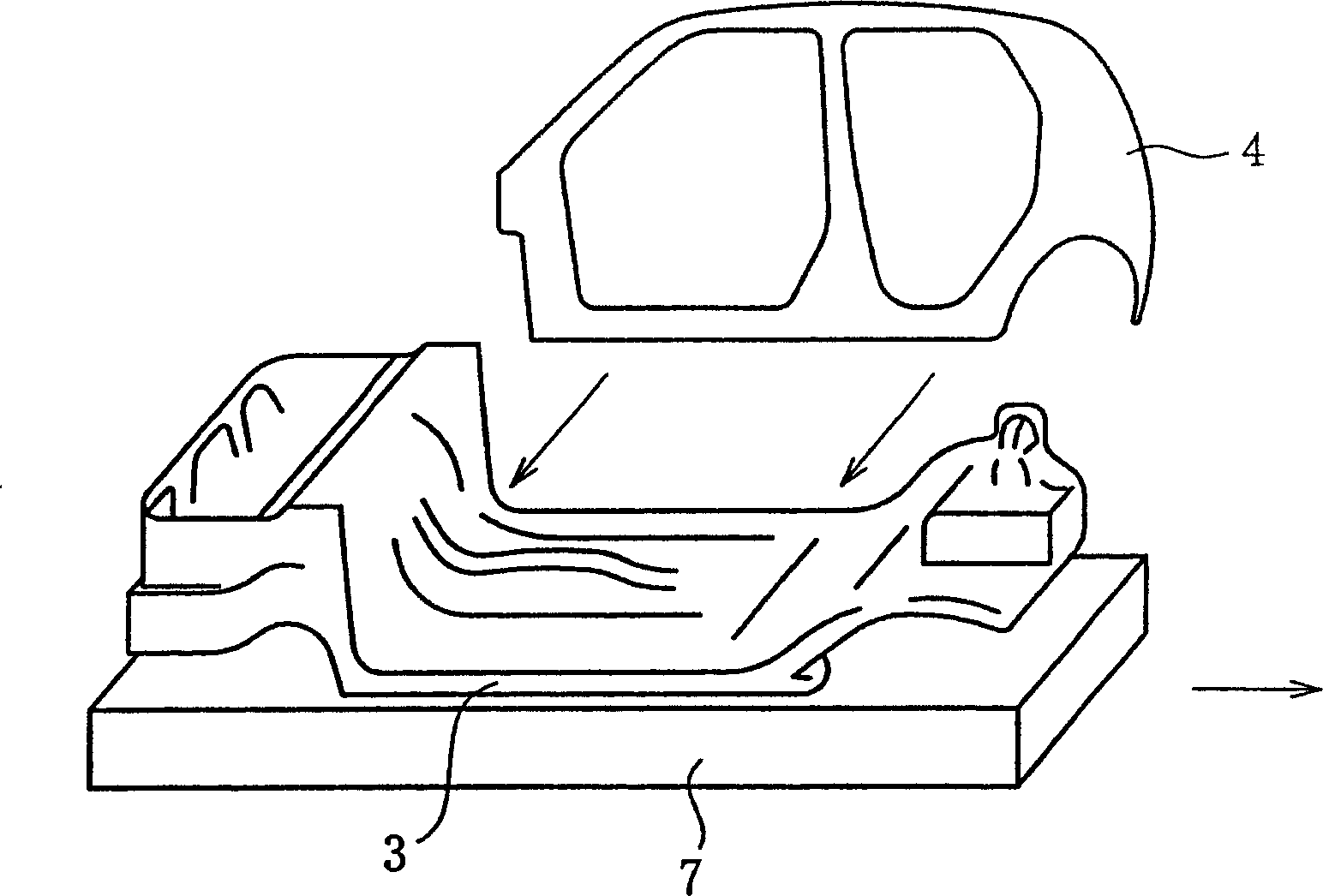
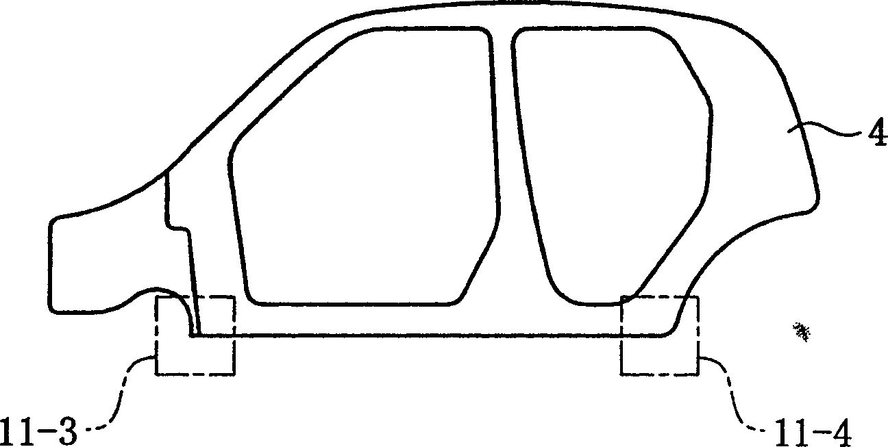
[0066]FIG. 1 is a simplified diagram of a side member assembly station implementing the present invention. As shown in FIG. 5 , the side member assembly station 1 is arranged at a designated position of the vehicle body production line. The side piece assembly station 1 is located upstream of the car body production line 2, that is, the bottom shell 3 production line shown in FIG. 2 . The rear end of the bodywork faces forward and is transferred to the side piece assembly station. In the sequence of the production line shown in Figure 5, downstream of the side member assembly station 1 is a rough roof placement station (roof coarse placement station) 5 and a roof assembly station 6 for completing the final welding edge of ...


PUM


Abstract

Objectives of the present invention are to reduce the size and weight of side-member and roof jigs, and to simplify analysis of problems related to ease-of-assembly of vehicle body roofs and side-members. In a first step, using clamping jigs through, a left and right pair of side-members are positioned with respect to an underbody (that was positioned at a prescribed position in a vehicle body assembly line ), and welded in place. Continuing in a second step, after the clamping jigs through have been released, a roof is placed on upper welding edges of the left and right side-members while being positioned using suspension jigs and, after which it is welded in place.

Description

technical field [0001] The present invention relates to a vehicle body assembly method, and in particular to an assembly method for (1) welding the left side part and the right side part to an underbody; (2) welding the left side part The method of assembling with the right side member in a bottom shell, and placing a cross-member such as a roof at the top of the two side members and welded in a completely separated place; and (3) used in Tack-welding is a method in which a top piece such as a roof, the front box (header) or the rear frame (frame-back) is located at the top of the left side piece and the right side piece and is arranged on a bottom shell. Background technique [0002] The main components of the car body include a bottom shell, left and right parts and a roof. The relative positions of these main components must be manipulated by using different positioning jigs, and the welding robot arm (welding robot) spot-welding (spot-welding) position is used, and then...

Claims


Application Information

Patent Timeline
Patent Type & Authority Applications(China)
IPC IPC(8): B23K11/11B23K37/02B23K37/04B62D65/02
CPCB23K2201/006B23K37/0229B23K37/0426B23K11/11B23K2101/006B62D65/04
Inventor 元见纯二喜多功那须信夫泉谷卓司赤木机池田和人荒山宽充
Owner DAIHATSU MOTOR CO LTD
Learn More