


Quick Research
Generate reliable direction feasibility study reports for your R&D in just a few steps.

Technical Q&A
Discover and master advanced knowledge NOW. Basics, ideas, possibilities, all at once.

Find Solutions
As an expert in R&D theories, this can generate solutions to your technical problems instantly.

Evaluate Feasibility
Analyze your overall solution with one click, know your potential R&D risks in advance.

Monitor Landscape
Get weekly tech updates, stay abreast of the latest tech innovations and key insights.
System and method for multi-channel mitigation of PMD/PDL/PDG
An optical signal, FEC-BECL technology, applied in the field of optical communication
- Summary
- Abstract
- Description
- Claims
- Application Information
AI Technical Summary
Problems solved by technology
Method used
Image

Examples
Embodiment Construction
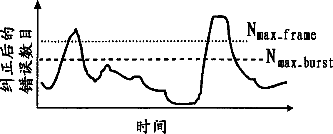
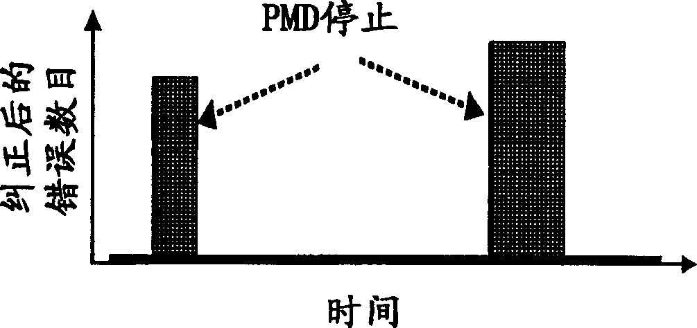
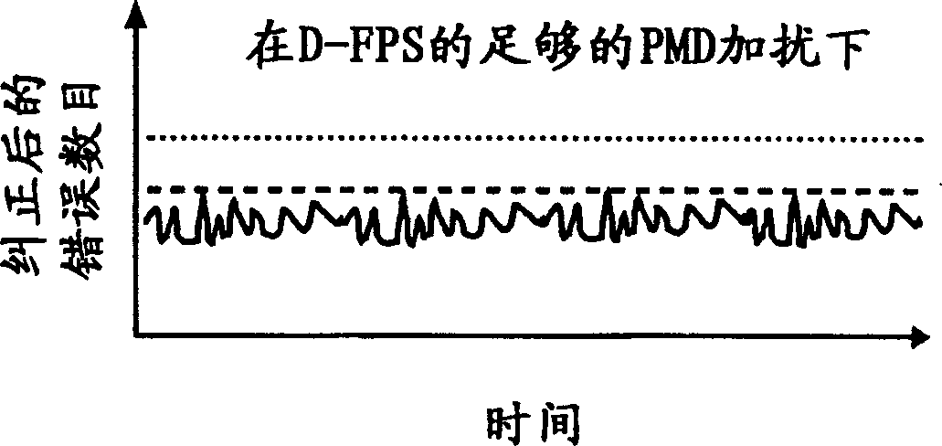
[0022] One aspect of the invention proposes to use FEC in combination with fast polarization scrambling to change the polarization of the signal between at least two states during each FEC Burst Error Correction Interval (BECP). By changing the link PMD at least once during each BECP, PMD-induced "stalls" are effectively limited to last for a time interval shorter than the correction time interval, so FEC can effectively correct errors of advantage that occur during the stall, given by Doing so for all wavelength channels simultaneously improves system tolerance to PMD, and prevents system stalls.
[0023] Figure 1A -D shows how the invention works. Figure 1A -B shows the situation without D-FPS. Such as Figure 1A - As shown in -B, PMD occasionally causes severe signal waveform distortion, which leads to continuous or very frequent errors. Such PMD-induced distortion can last from milliseconds to minutes.
[0024] For any given FEC code, there is a maximum number of corre...
PUM
 Abstract
Description
Claims
Application Information
 - R&D Engineer
- R&D Manager
- IP Professional
- Industry Leading Data Capabilities
- Powerful AI technology
- Patent DNA Extraction
Browse by: Latest US Patents, China's latest patents, Technical Efficacy Thesaurus, Application Domain, Technology Topic, Popular Technical Reports.
© 2024 PatSnap. All rights reserved.Legal|Privacy policy|Modern Slavery Act Transparency Statement|Sitemap|About US| Contact US: help@patsnap.com