


Quick Research
Generate reliable direction feasibility study reports for your R&D in just a few steps.

Technical Q&A
Discover and master advanced knowledge NOW. Basics, ideas, possibilities, all at once.

Find Solutions
As an expert in R&D theories, this can generate solutions to your technical problems instantly.

Evaluate Feasibility
Analyze your overall solution with one click, know your potential R&D risks in advance.

Monitor Landscape
Get weekly tech updates, stay abreast of the latest tech innovations and key insights.
Luminous diode
A technology of light-emitting diodes and surface electrodes, applied in electrical components, electrical solid-state devices, circuits, etc., can solve the problems of reduced transparency, unreliability, discoloration of transparent seals, etc.
- Summary
- Abstract
- Description
- Claims
- Application Information
AI Technical Summary
Problems solved by technology
Method used
Image

Examples
Embodiment Construction
[0019] A preferred embodiment of a light emitting diode according to the present invention will be explained with reference to the accompanying drawings.
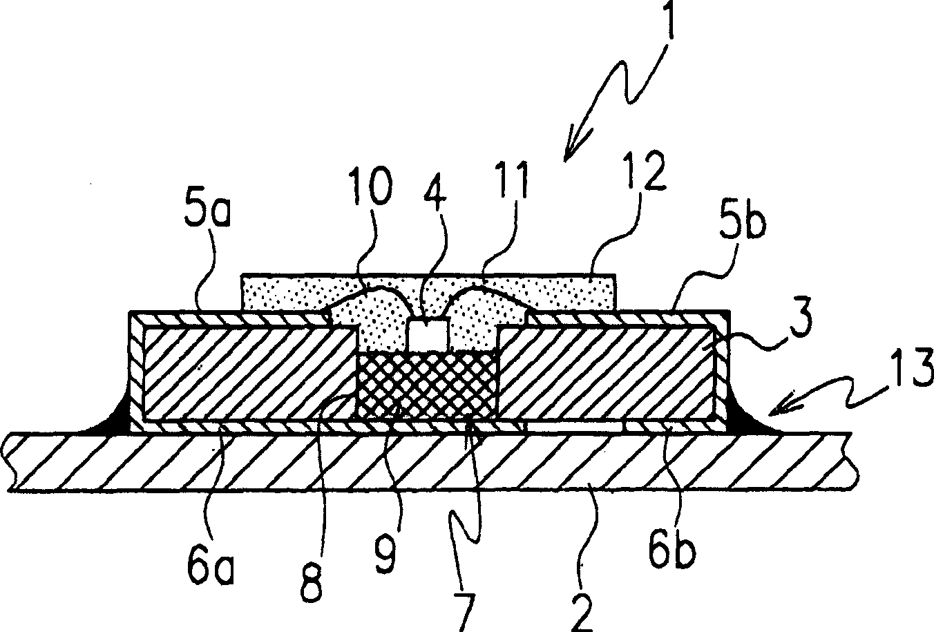
[0020] figure 1 The light emitting diode 1 of the first embodiment of the present invention will be described by way of example.
[0021] The light emitting diode 1 includes an LED chip 4, an insulating circuit substrate 3 in which the LED chip 4 is placed, and a printed wiring board 2. The insulating circuit substrate 3 is made of glass epoxy, silicone or the like.
[0022] Provided on the circuit substrate 3 are a pair of integrally formed upper and lower surface electrodes 5a, 6a and 5b, 6b.
[0023] The circuit substrate 3 has a heat radiation mechanism 7 . Radiation mechanism 7 comprises a heat radiation part 9, and it is in figure 1 is arranged in the storage portion 8 formed in the substantially central portion of the circuit substrate 3 in the embodiment shown in . The storage portion 8 includes, for example, a ...
PUM
 Abstract
Description
Claims
Application Information
 - R&D Engineer
- R&D Manager
- IP Professional
- Industry Leading Data Capabilities
- Powerful AI technology
- Patent DNA Extraction
Browse by: Latest US Patents, China's latest patents, Technical Efficacy Thesaurus, Application Domain, Technology Topic, Popular Technical Reports.
© 2024 PatSnap. All rights reserved.Legal|Privacy policy|Modern Slavery Act Transparency Statement|Sitemap|About US| Contact US: help@patsnap.com