
Lifting device

A lifting device and lifting reel technology, applied in portable lifting devices, hoisting devices, spring mechanisms, etc., can solve the problems of large mechanical alternating stress of the belt, and achieve the effect of small mechanical alternating stress

Inactive Publication Date: 2005-02-09
艾森曼机械制造两合公司(无限责任股东:艾森曼-基金会)
View PDF0 Cites 2 Cited by
  • Summary
  • Abstract
  • Description
  • Claims
  • Application Information

AI Technical Summary

Problems solved by technology

[0008] However, in the lifting devices of this type known on the market, the mechanical alternating stress of the belt is still relatively large when it is wound on or unwound from the lifting drum

Method used


Image

  • Lifting device
  • Lifting device
  • Lifting device

Examples


Embodiment Construction

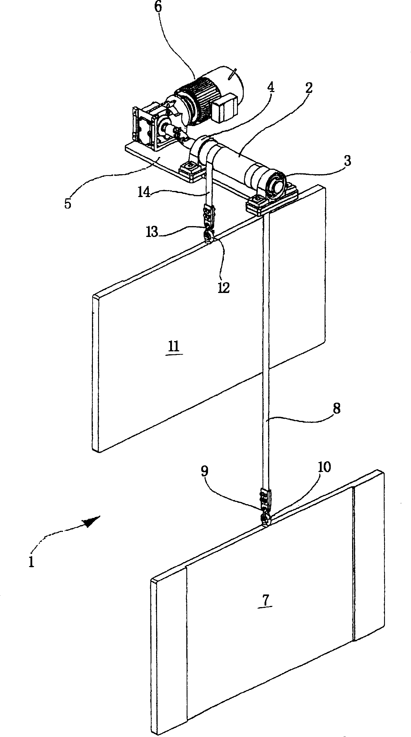
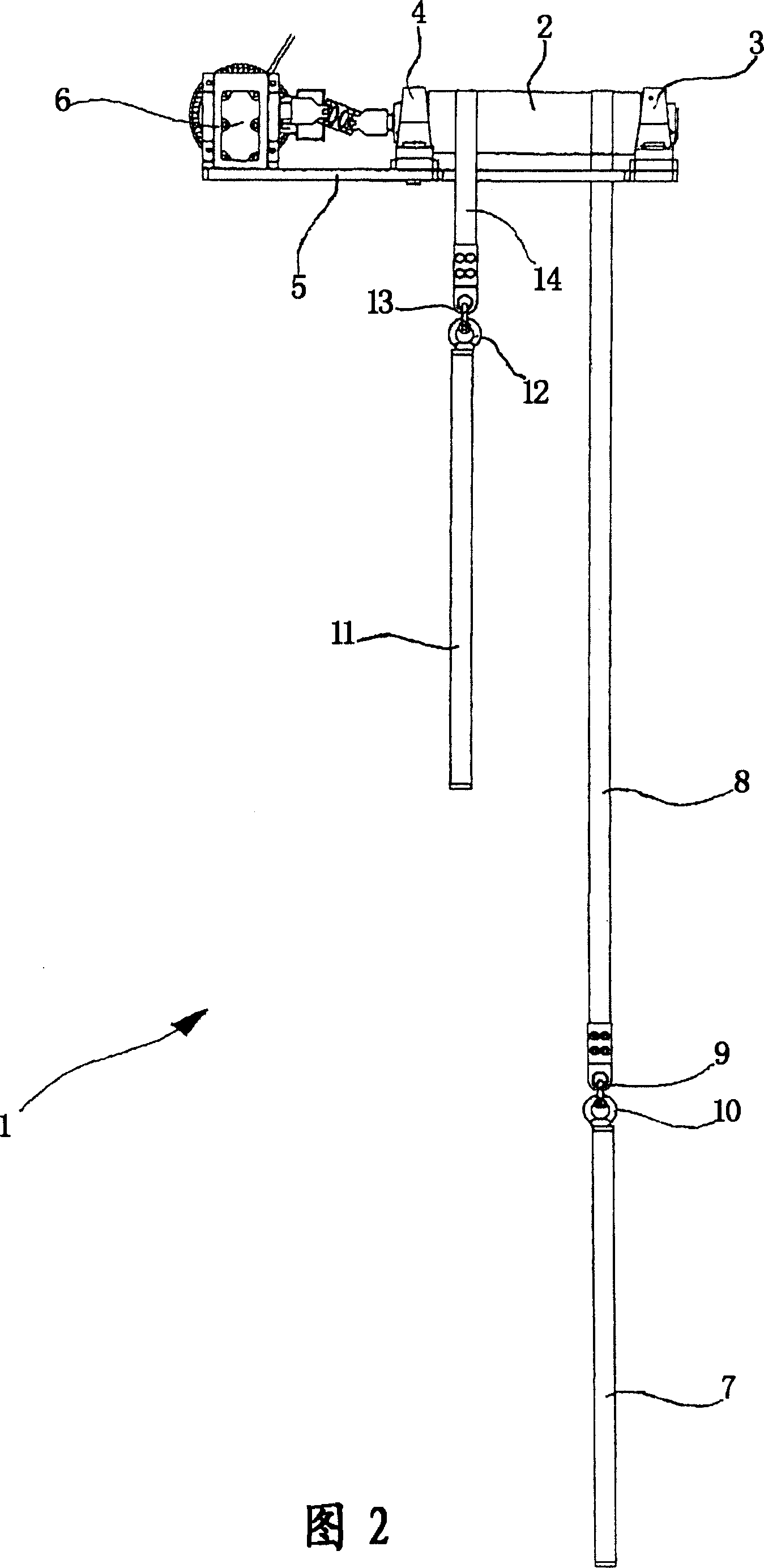
[0024] exist figure 1 The lifting device shown in a schematic perspective view and generally designated 1 comprises a lifting drum 2 , which is itself rotatably mounted on a mounting platform 5 via bearings 3 , 4 . The lifting drum 2 can be rotated in both directions by means of an electric motor 6 which is likewise fastened to the mounting platform 5 . The installation platform 5 is arranged at a certain height above the floor of the room, for example by means of a steel structure not shown for the sake of clarity.

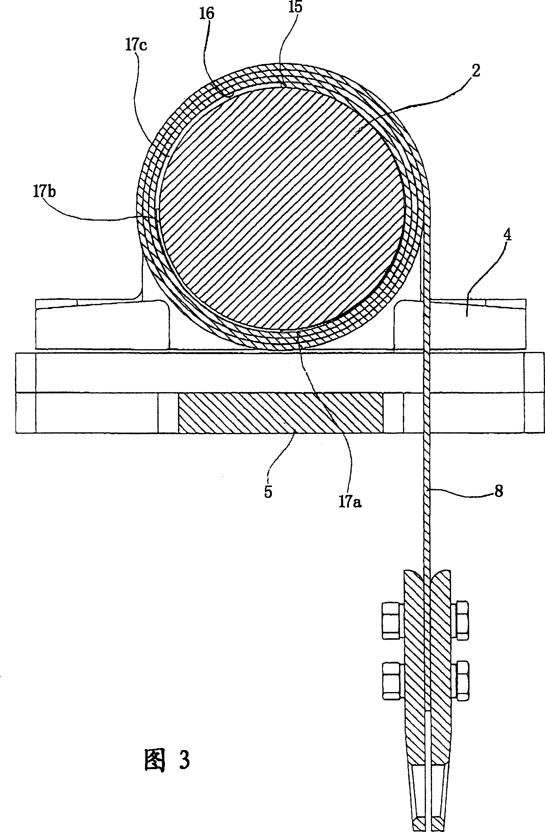
[0025] A load, shown schematically as plate 7 , is suspended on lifting drum 2 via a steel belt 8 . To this end, the steel belt 8 has at its lower end a safety hook 9 which can be inserted into a lifting lug 10 of the load 7 . The upper end of steel band 8 is fixed on the lifting reel 2. When the lifting drum 2 rotates, the steel strip 8 is wound on the lifting drum 2 more or less in mutually superimposed turns, or is unwound from this drum depending on the di...


PUM


Abstract

A lifting device for raising and lowering a load comprises in a known manner a lifting drum that can be driven in both directions of rotation, as well as at least one belt serving as traction mechanism that is secured to one end of the lifting drum and carries at the other end a holding device for the load. The belt can be wound on the lifting drum by rotation of the latter, in such a way that the windings come to lie on top of one another. In order to reduce repeated mechanical stress reversals at the step that is formed by the end of the belt secured to the circumferential wall of the lifting drum, at least one spacing element is arranged on the circumferential wall of the lifting drum, against which element rests the first winding of the belt.

Description

technical field [0001] The invention relates to a lifting device for lifting and lowering a load, which has [0002] a) a lifting drum; [0003] b) a driving device, by means of which the lifting drum can be rotated in two directions; [0004] c) at least one strap used as a traction device, said strap being fixed at one end to the lifting drum and having a holding device for the load at the other end; [0005] in, [0006] d) The belt can be wound on the drum by rotation of the lifting drum in such a way that one turn is superimposed on the other. Background technique [0007] Lifting devices are known in various configurations which work with a lifting drum and at least one flexible traction device wound on the lifting drum. In particular ropes, chains and belts are used as traction means. The belt has the advantage that it can be wound on the lifting drum in a particularly well-defined manner and has a relatively high load-bearing capacity, while still remaining suff...

Claims


Application Information

Patent Timeline
Patent Type & Authority Applications(China)
IPC IPC(8): B66D1/34B66D3/26
CPCB66D1/34B66D3/26
Inventor F·埃伦雷特纳
Owner 艾森曼机械制造两合公司(无限责任股东:艾森曼-基金会)
Learn More