
Mini DC motor

A DC motor and motor technology, applied in the shape/style/structure of winding insulation, can solve the problems of high production cost and defective rate, and achieve the effect of improving production efficiency, improving insulation effect and increasing winding space

Inactive Publication Date: 2005-01-19
萃进有限公司
View PDF0 Cites 3 Cited by
  • Summary
  • Abstract
  • Description
  • Claims
  • Application Information

AI Technical Summary

Problems solved by technology

[0005] When using the method of coating the end face and inner surface of the iron core with insulating material, due to the processing equipment and processing method, the production cost and defective rate are relatively high, especially for the rotor core with an outer diameter of φ5.0mm or less

Method used


Image

  • Mini DC motor
  • Mini DC motor
  • Mini DC motor

Examples


Embodiment Construction

[0025] see below Figures 5a-5b and 6a-6b, describe preferred embodiments of the invention. In Figures 5 and 6, with figure 1 The corresponding parts in -4 adopt the same reference numerals.

[0026] Figures 5a-5b shows the state in which the rotor of the present invention is stretched when the insulating sheet is installed. Such as Figures 5a-5b As shown in , it is assumed that the gap between the edge of the insulating sheet 111 bent at right angles and the iron core is T1, the thickness of the edge of the insulating sheet 111 is T2, and the width of the folded edge of the insulating sheet 111 is H1. from Figure 5a It can be seen from the figure that in the pre-stretched state of the insulating sheet 111, there is obviously a gap T1 between the edge of the insulating sheet 111 and the iron core. If this gap T1 is allowed to exist, the space for installing the coil will be reduced, which will affect the motor. efficiency, it is even difficult to manufacture rotors wi...


PUM


Abstract

The invention provides a microtype DC machine rotor and its making method, including a rotor iron core and a rotating shaft through the center of the iron core, where there are wire slots for winding coil, axially made on the iron core, two ends of the rotor iron core are both installed with an insulating piece concentric with the iron core, and the extended edge round the wire slot of each insulating piece is bent at a right angle to the inside of the wire slot.

Description

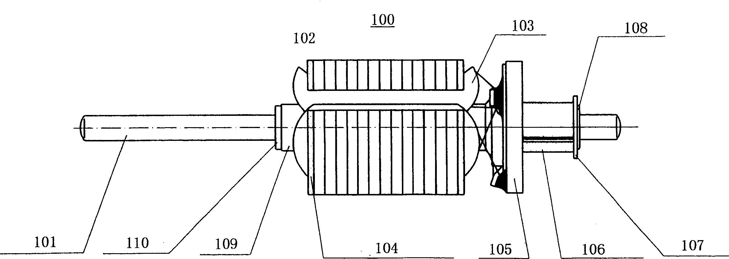
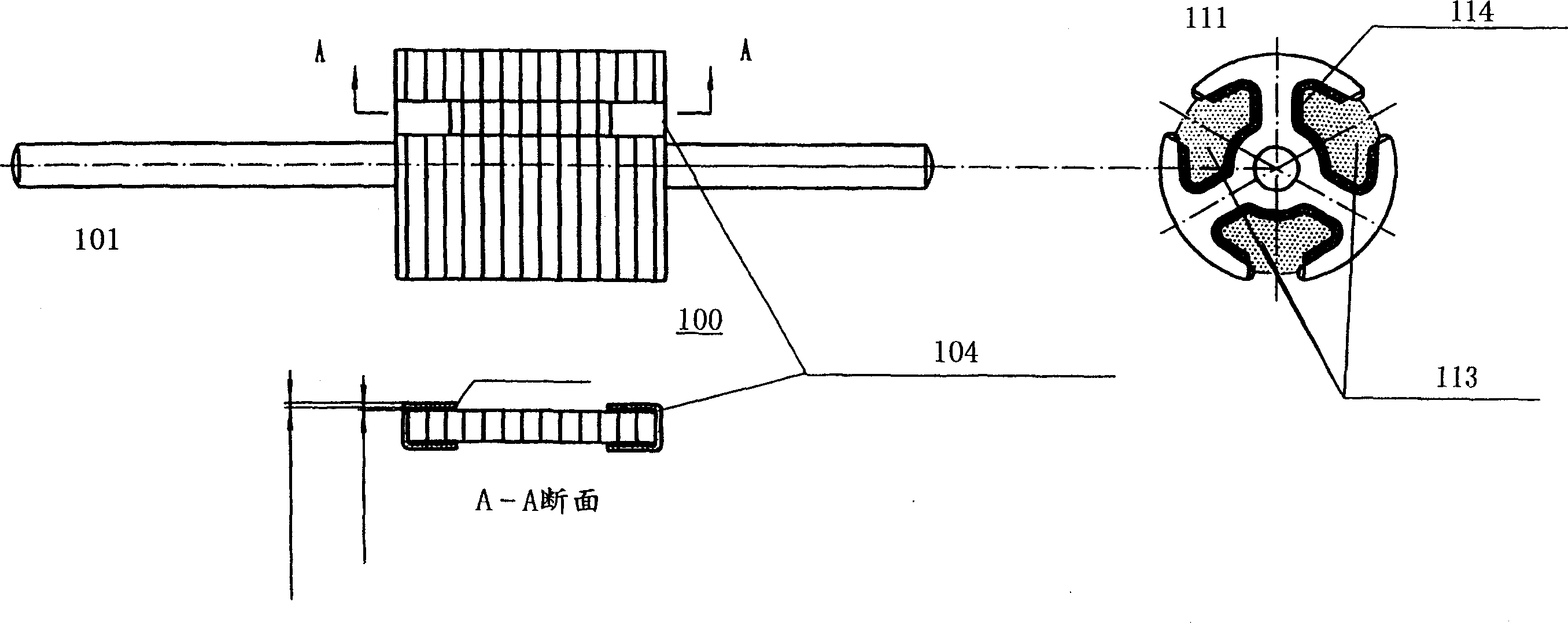
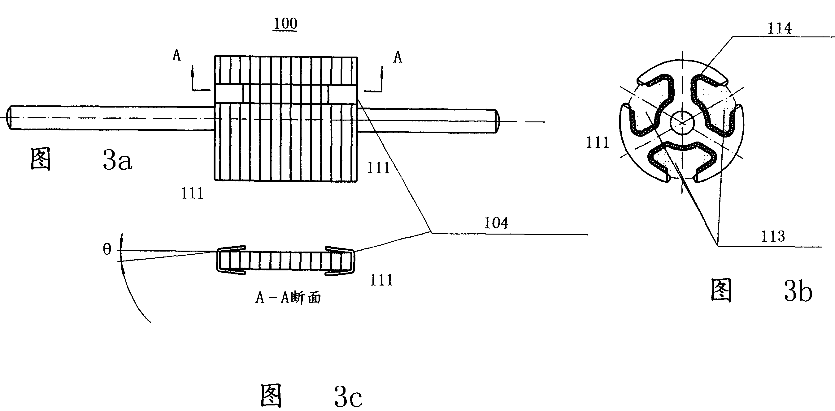
technical field [0001] The invention relates to a micro motor. Specifically, the present invention relates to rotors for miniature DC motors. Background technique [0002] A traditional miniature DC motor consists of a stator and a rotor. The rotor 100 includes a rotating shaft 101 , a rotor core 102 composed of silicon steel sheets stacked concentrically on the rotating shaft 101 , and a rotor winding 103 is wound on the iron core. One end of the rotating shaft 101 is equipped with a rheostat 105 , a commutator 106 , an oil stop washer 107 and an adjusting washer 108 , and the other end of the rotating shaft 101 is equipped with a thrust sleeve 109 and an adjusting washer 110 . The shape of the rotor 100 is as figure 1 as shown in . In order to prevent conduction between the rotor winding 103 and the core 102 of the rotating core; the common method is to install insulating sheets or insulating coatings 104 at both ends of the iron core, see figure 2 a, 2b and Figures ...

Claims


Application Information

Patent Timeline
IPC IPC(8): H02K3/34
Inventor 曾雪松
Owner 萃进有限公司
Learn More