Beauty device
A beauty appliance and roller technology, applied in the field of beauty appliances, can solve problems such as difficulty in obtaining massage effect and easy reduction of pressure on the skin surface by the roller, and achieve good feeling of use, ease of use, and high massage effect
- Summary
- Abstract
- Description
- Claims
- Application Information
AI Technical Summary
Problems solved by technology
Method used
Image
Examples
Embodiment 1
[0077] Examples of the beauty device will be described below.
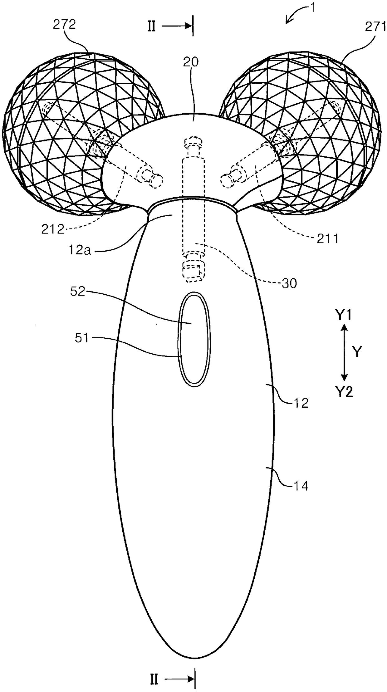
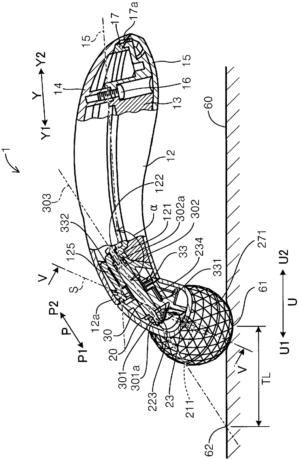
[0078] Such as figure 1 , figure 2 As shown, the beauty device 1 of the first embodiment includes a handle 12 , a roller unit 20 and a roller unit shaft 30 .
[0079] Two rollers 271 , 272 are rotatably provided on the roller unit 20 .
[0080] The roller unit shaft 30 is interposed between the roller unit 20 and the handle 12 and rotatably supports the roller unit 20 with respect to the handle 12 .
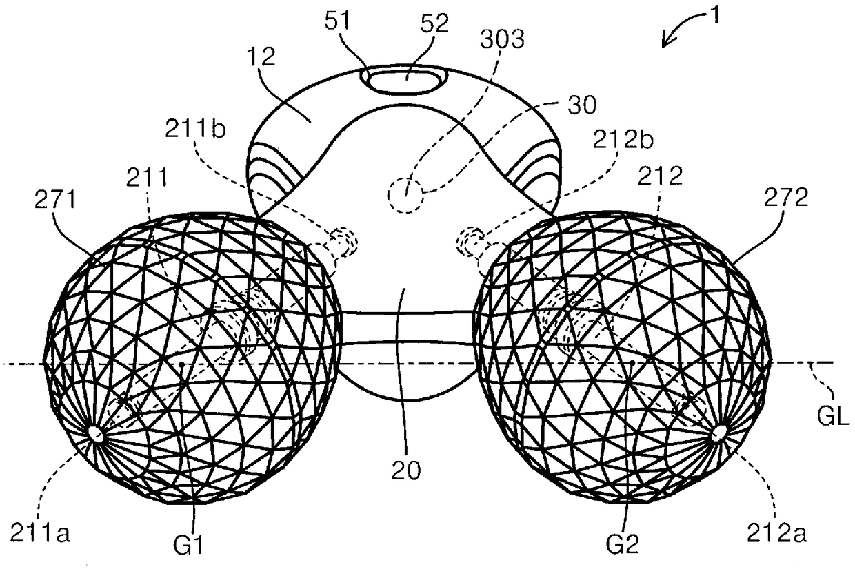
[0081] Furthermore, if image 3 As shown, when viewed from the axial direction P of the roller unit shaft 30 , the axis 303 of the roller unit shaft 30 is located away from the virtual straight line GL passing through the two centers of gravity G1 , G2 of the two rollers 271 , 272 .
[0082] Hereinafter, the beauty device 1 of this Example is demonstrated in detail.
[0083] Such as figure 1 As shown, the beauty device 1 includes a substantially rod-shaped handle 12 and a roller unit 20 located at the longit...
Embodiment 2
[0108] The beauty device 1 of embodiment 1 includes a roller unit 20, but the beauty device 1 of embodiment 2 includes such as Figure 11 A pair of roller units 201, 202 are shown. Each of the pair of roller units 201 and 202 has the same structure as the roller unit 20 of the first embodiment. Furthermore, centers of gravity G1, G2, G3, and G4 of the four rollers 271, 272, 273, and 274 included in the pair of roller units 201, 202 are located on the same plane. Additionally, if Figure 11 As shown, a pair of roller units 201, 202 are arranged symmetrically on the basis of a virtual straight line L1 passing through the center of the handle 12, so that the axes of the respective roller unit shafts 30 lie on the same plane S1. like Figure 12 As shown, in this embodiment, the angle γ formed by the axes 303 of the respective roller unit shafts 30 on the same plane is 120°.
[0109] According to the cosmetics device 1 of this Example, since center-of-gravity G1-G4 of four roll...
Embodiment 3
[0111] The beauty device 1 of embodiment 2 comprises a pair of roller units 20, such as Figure 13 As shown, the beauty device 1 of the third embodiment includes two pairs of roller units 201 , 202 , 203 , and 204 . Each of the two pairs of roller units 201 , 202 , 203 , 204 has the same structure as the roller unit 20 of the first embodiment.
[0112] Furthermore, if Figure 13 As shown, in the two pairs of roller units 201, 202, 203, 204 of the present embodiment, at one end side of the handle 12, when viewed from above, the axis 303 of the roller unit shaft 30 of the pair of roller units 201, 202 is located at the same position as the handle. On the imaginary straight line L3 perpendicular to the longitudinal direction Y of the handle 12, it is arranged symmetrically with the center line L2 of the longitudinal direction Y of the handle 12 as a reference. On the other hand, at the other end side of the handle 12, when viewed from above, the axis 303 of the roller unit shaf...
PUM
 Abstract
Description
Claims
Application Information
 - R&D
- Intellectual Property
- Life Sciences
- Materials
- Tech Scout
- Unparalleled Data Quality
- Higher Quality Content
- 60% Fewer Hallucinations
Browse by: Latest US Patents, China's latest patents, Technical Efficacy Thesaurus, Application Domain, Technology Topic, Popular Technical Reports.
© 2025 PatSnap. All rights reserved.Legal|Privacy policy|Modern Slavery Act Transparency Statement|Sitemap|About US| Contact US: help@patsnap.com


