Supporting stand frame, method for manufacturing color selecting frame, cathode-ray tube
A technology for cathode ray tubes and manufacturing methods, applied in the direction of cathode ray tubes/electron beam tubes, non-luminescent electrode manufacturing, discharge tubes, etc., capable of solving problems such as aperture grid 20 wrinkles, cathode ray tube discomfort, etc., and achieving high precision Positioning, the effect of suppressing a decrease in rigidity
- Summary
- Abstract
- Description
- Claims
- Application Information
AI Technical Summary
Problems solved by technology
Method used
Image
Examples
Embodiment approach 1
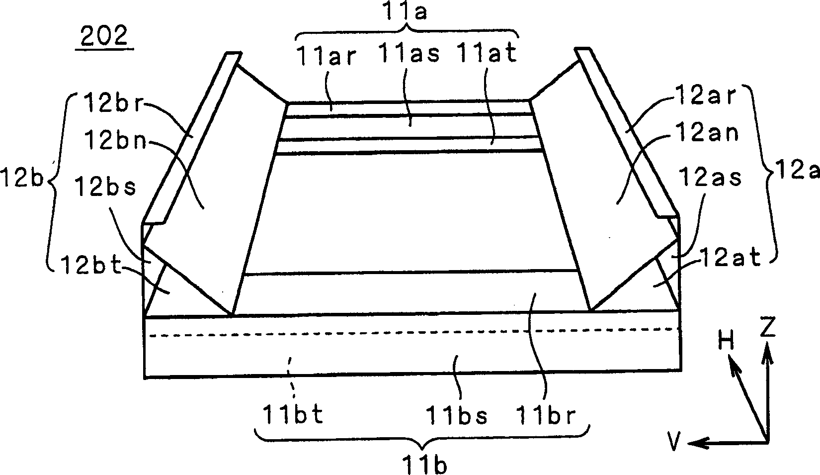
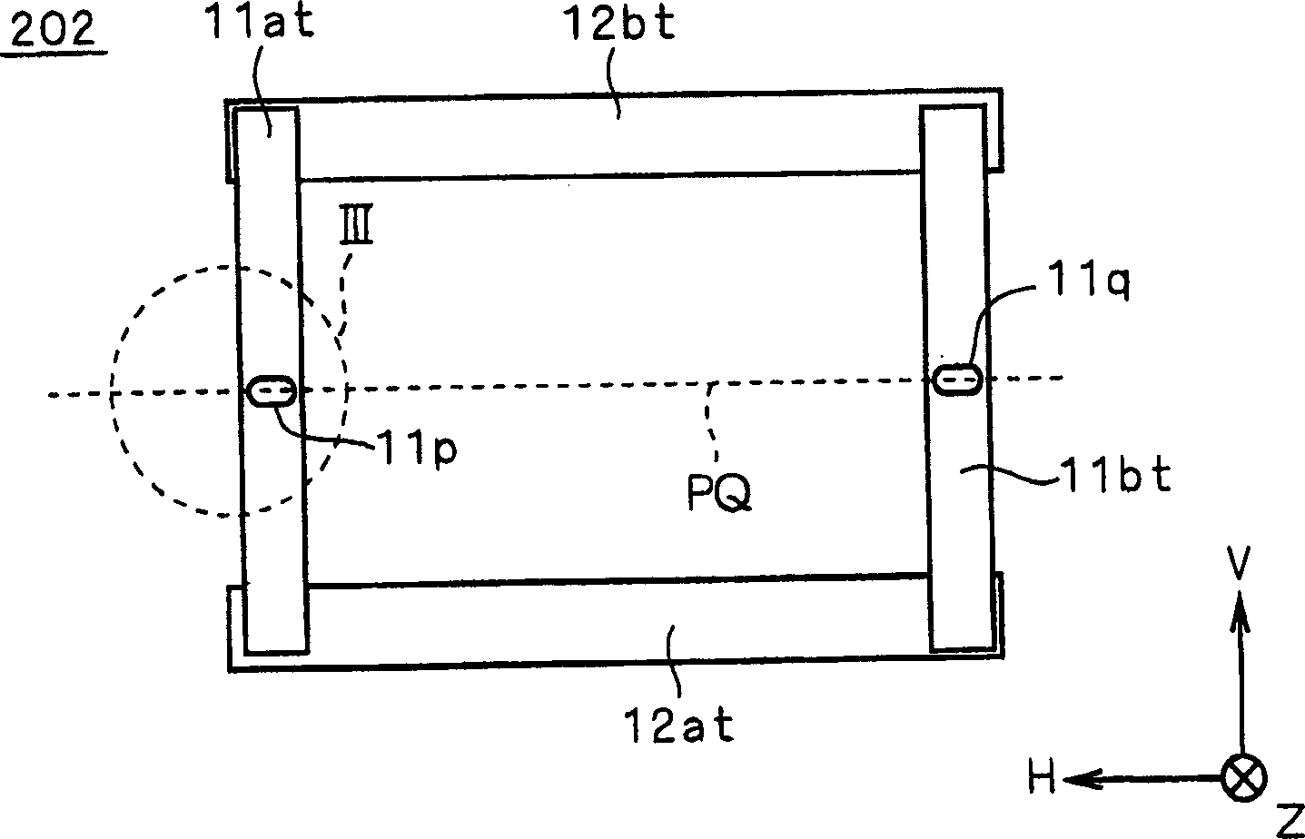
[0059] figure 1 is a conceptual diagram showing the structure of the stent skeleton 202 according to Embodiment 1 of the present invention. Like the stent skeleton body 201 , the stent skeleton body 202 has the horizontal support pair 12 supporting the aperture grid along the horizontal direction H, and the vertical support pair 11 supporting the horizontal support pair 12 . Each of the horizontal support pairs 12 has water supports 12a, 12b extending in the horizontal direction H, and each of the vertical support pairs 11 has vertical supports 11a, 11b extending in the vertical direction. For example, the vertical support pair 11 and the horizontal support pair 12 are welded to each other.
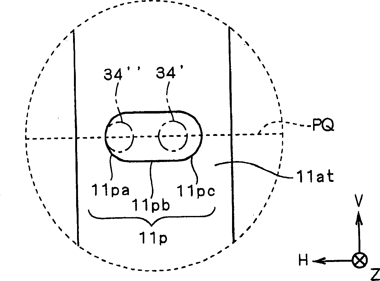
[0060] However, in this embodiment, the structure of the horizontal support body 12a, 12b and the vertical support body 11a, 11b is different compared with the prior art. The horizontal support 12a has surfaces 12ar, 12at perpendicular to the traveling direction Z, a surface 12as perpe...
Embodiment approach 2
[0079] For positioning in the direction of travel Z, the positioners in contact with the surfaces 11ar, 11br of the vertical support pair 11 do not necessarily have to be plate-shaped like the positioner 39 .
[0080] Figure 7 It is a conceptual diagram of the positioning of the stent skeleton body 202 along the traveling direction Z according to Embodiment 2 of the present invention. In this embodiment, if Figure 7 As shown, positioners 38a-38c are used. During positioning along the traveling direction Z, the positioner 38a contacts the surface 11ar of the vertical support 11a, and during positioning along the traveling direction Z, the positioners 38b, 38c contact the surface 11br of the vertical support 11b. In this way, as long as the positioning in the horizontal direction H and the vertical direction V before the positioning along the traveling direction Z is not damaged, the movement of the support frame body 202 to the traveling direction Z can be brought into cont...
Embodiment approach 3
[0082] Figure 8 shows the structure of the stent skeleton body 202 according to Embodiment 3 of the present invention, which corresponds to figure 2 Enlarged view of part III. In this embodiment, the outline of the positioning hole 11p is substantially triangular, and the arc portion 11pa shown in Embodiment 1 is provided, and the side 11pe facing it is provided, and a pair of two ends of the arc portion 11pa and the side 11pe are connected. Edge 11pd. The arc portion 11pa faces the side 11pe on the side opposite to the vertical support 11b, and the side 11pe is arranged substantially perpendicular to the virtual line PQ. For example, the outline of the positioning hole 11p is an isosceles triangle with the side 11pe as the base. The positioning hole 11q has the same shape as the positioning hole 11p.
[0083] In this embodiment, and in Embodiment 1, use image 3 Compared with the positioning hole 11p described above, a side 11pe wider than the arc portion 11pc in the v...
PUM
 Abstract
Description
Claims
Application Information
 - R&D
- Intellectual Property
- Life Sciences
- Materials
- Tech Scout
- Unparalleled Data Quality
- Higher Quality Content
- 60% Fewer Hallucinations
Browse by: Latest US Patents, China's latest patents, Technical Efficacy Thesaurus, Application Domain, Technology Topic, Popular Technical Reports.
© 2025 PatSnap. All rights reserved.Legal|Privacy policy|Modern Slavery Act Transparency Statement|Sitemap|About US| Contact US: help@patsnap.com


