


Quick Research
Generate reliable direction feasibility study reports for your R&D in just a few steps.

Technical Q&A
Discover and master advanced knowledge NOW. Basics, ideas, possibilities, all at once.

Find Solutions
As an expert in R&D theories, this can generate solutions to your technical problems instantly.

Evaluate Feasibility
Analyze your overall solution with one click, know your potential R&D risks in advance.

Monitor Landscape
Get weekly tech updates, stay abreast of the latest tech innovations and key insights.
Suspending dental crown type implanting tooth
A technology for dental implants and dental crowns, applied in dental implants, dentistry, dental prosthetics, etc., can solve problems such as excessively low resistance forms, and achieve the effect of inducing the formation of osteoblasts, prolonging the retention time, and overcoming defects and deficiencies
- Summary
- Abstract
- Description
- Claims
- Application Information
AI Technical Summary
Problems solved by technology
Method used
Image

Examples
Embodiment Construction
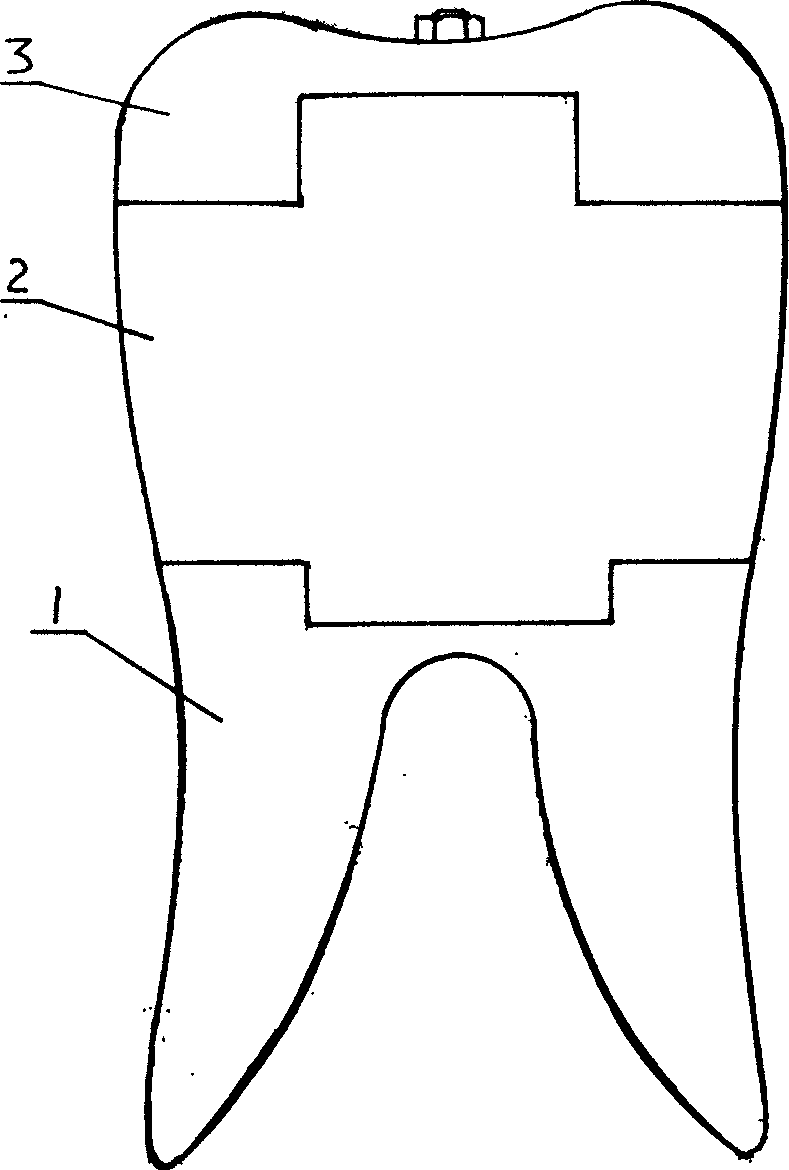
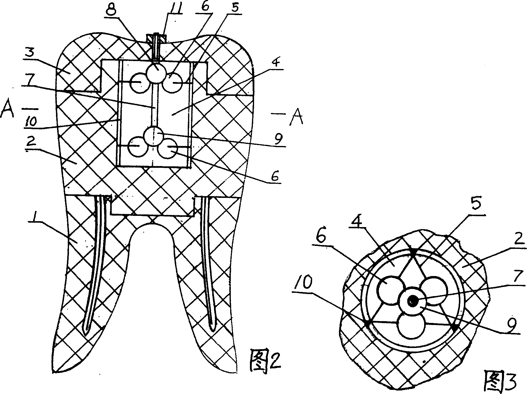
[0015] Suspension crown type dental implant, including the root 1 with the root canal inside, the tooth post 2 pierced into the root canal by the post and the crown 3 on the upper part of the post; there is a concave cavity 4 on the upper end of the post , the cavity is fixed with a stressed elastic buffer device, which includes a triangular prism frame 5 connected by elastic rubber rods, and rubber is fixed on each transverse rubber rod on the upper and lower end faces of the triangular prism frame. The ball 6, the stressed elastic buffering device also includes a connecting thin rod 7, which is inserted into the rubber balls which are respectively located on the upper and lower end surfaces of the triangular prism frame and are in contact with the rubber balls on the upper and lower end faces of the triangular prism frame. On the two rubber balls 8 and 9, a groove 10 corresponding to the position of the vertical rubber rod of the triangular prism frame is opened on the inner ...
PUM
 Abstract
Description
Claims
Application Information
 - R&D Engineer
- R&D Manager
- IP Professional
- Industry Leading Data Capabilities
- Powerful AI technology
- Patent DNA Extraction
Browse by: Latest US Patents, China's latest patents, Technical Efficacy Thesaurus, Application Domain, Technology Topic, Popular Technical Reports.
© 2024 PatSnap. All rights reserved.Legal|Privacy policy|Modern Slavery Act Transparency Statement|Sitemap|About US| Contact US: help@patsnap.com