
Method and device for extruding curved extrusion profiles

A technology of extruded profiles, extrusion methods, applied in the field of extrusion and installation of curved extruded profiles

Inactive Publication Date: 2004-11-24
SMS欧姆科股份有限公司
View PDF1 Cites 3 Cited by
  • Summary
  • Abstract
  • Description
  • Claims
  • Application Information

AI Technical Summary

Problems solved by technology

However, the precondition is that the output area must be free at all times for a subsequent profile

Method used


Image

  • Method and device for extruding curved extrusion profiles
  • Method and device for extruding curved extrusion profiles

Examples


Embodiment Construction

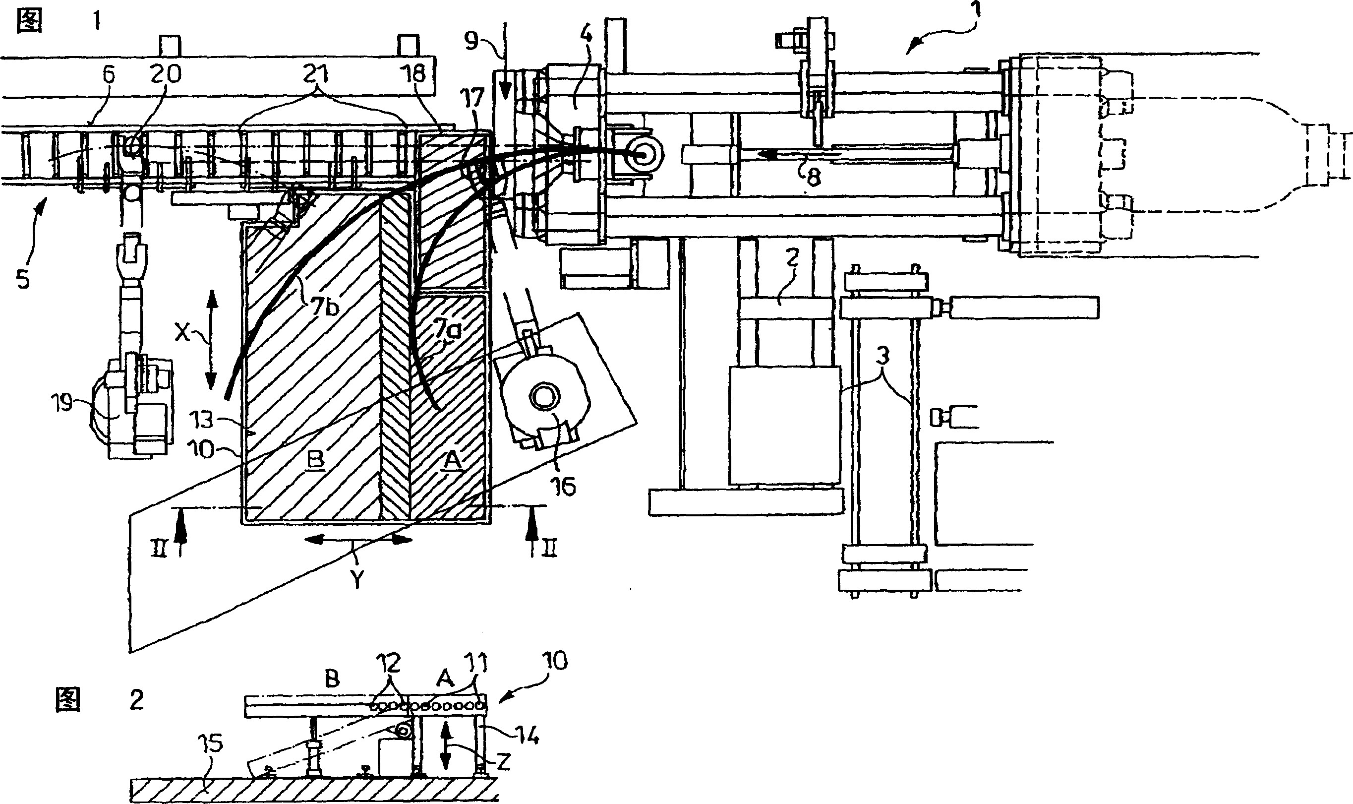
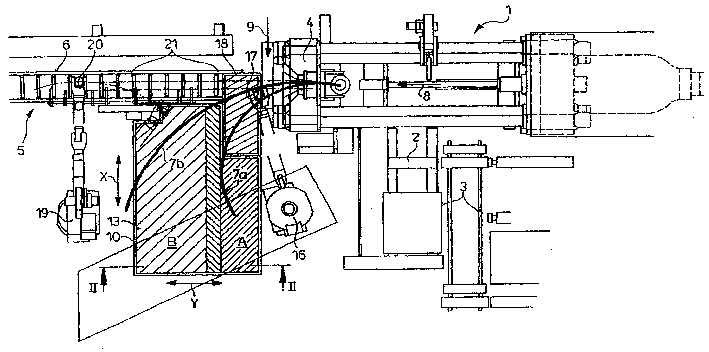
[0022] The blank 2 to be extruded is supplied to an extrusion machine 1 as shown in FIG. 1 by means of a charging device 3 . The profile strip extruded through the forming extrusion die exits the front cross member 4 and, during linear extrusion, arrives on an exit roller table 6 arranged at the exit 5 of the extruder.

[0023] In this exemplary embodiment, however, rounded profile strips 7 a , 7 b are produced which, relative to the straight extrusion direction 8 , have a constant curvature towards one side. When bending the strip with a desired radius, wherein in FIG. 1 for example the profiled strip 7a or 7b is shown with two different radii, there is an arrow 9 between the front beam 4 and the delivery roller table 6 and Correspondingly, there is a guiding tool which acts on the web and which can cooperate with a further, not shown, upstream radius sensor.

[0024] On the side corresponding to the bending direction of the profiled strips 7a, 7b, a support frame or support...


PUM


Abstract

The invention relates to a method for extruding curved extrusion products (7a, 7b), whereby the extruded profile is formed in a die that is located upstream of a crosshead (4) of an extrusion installation (1) and is subsequently curved or bent by the action of external forces. The extruded strand (7a, 7b) is taken up at the press outlet by a bearing surface (10) that supports the underside of the strand. Once a partial length of strand has been separated, said length is moved (10) from the press flow and is transported away by the bearing surface, whereby the provision of a supporting surface for the subsequent strand is simultaneously maintained during said transportation by the bearing surface (10). To achieve this, a platform (10) that is located in the press outlet (5), that supports the extruded strand and that can be raised and lowered is divided into functional fields (A, B). The rear functional field (B), which adjoins the front functional field (A) closest to the machine, can be temporarily pivoted into an inclined position in relation to the base.

Description

technical field [0001] The present invention relates to a method and an apparatus for extrusion of curved extruded profiles, wherein the extruded profiles are formed in an extrusion die arranged in front of the extruder front crossbeam and subsequently bent or bent by external force and extruded The processing line is cut into segments. Background technique [0002] When conveying the extruded profiles produced on the strip extruder or more precisely the tube extruder or combined tube extruder, the output direction is determined according to the production plan. Therefore, when extruding rods, profiles, pipes and hollow profiles, the unit is designed for linear extrusion, while when manufacturing wire it must be equipped for pressing in the subsequent coiler. When extruding in a straight line, for example, there is a section of undriven roller table behind the front cross member. During the coiling process, this section of the roller table is moved sideways to make room fo...

Claims


Application Information

Patent Timeline
IPC IPC(8): B21C35/00B21C23/12
CPCB21C23/12
Inventor U·穆沙利克N·雅各比J·R·坎普
Owner SMS欧姆科股份有限公司
Learn More