
Burst mode optical receiver

An optical receiver and burst mode technology, which is applied in electromagnetic receivers, electromagnetic wave transmission systems, electrical components, etc., can solve the problems that circuits cannot use burst optical reception, coupling capacitors are fully discharged, and data packets lose symbols, etc. , to achieve the effect of avoiding the loss of small signal data packet symbols

Active Publication Date: 2004-11-10
WUHAN TELECOMM DEVICES
View PDF1 Cites 9 Cited by
  • Summary
  • Abstract
  • Description
  • Claims
  • Application Information

AI Technical Summary

Problems solved by technology

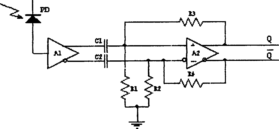
Therefore, this circuit cannot be used for burst-type optical reception, because in burst-type reception, when a large optical power data packet ends, and then a small optical power data packet arrives, because the coupling capacitor cannot Fully discharge within the packet interval time (8-10 bits), if a data packet with a small optical power comes next, many symbols will be lost at the front of the data packet (such as Figure 4 shown)

Method used


Image

  • Burst mode optical receiver
  • Burst mode optical receiver
  • Burst mode optical receiver

Examples


Embodiment Construction

[0020] The present invention will be further described below in conjunction with the accompanying drawings and examples, but these examples should not be construed as limiting the present invention.

[0021] The present invention sees the circuit from a single channel is a capacitive coupling limiting amplifier circuit, under the control of the electronic switch 103, the output signal of the preamplifier 101 alternately inputs two channels (channel 1, channel 2), and each channel is working After a data packet, it will "rest" for a data packet time, during which the charges on the coupling capacitors C1, C2 (C3, C4) can be fully discharged, so that it will not affect the reception of the next small signal data packet , so as to solve the contradiction between poor receiving optical path loss and receiving sensitivity. The circuit of the invention can fully meet the index requirement of ITU-T G.983.1 Class C for burst reception.

[0022] see Figure 5 The optical signal is co...


PUM


Abstract

The invention relates to a burst mode optical receiver, composed of a detector, a preamplifier, and two capacitor coupled judgment circuit channels, and its character: there is also an electronic switch set between the preamplifier and the two channels, the electronic switch is connected with a control circuit, the input end of the electronic switch is connected with the output end of the preamplifier, and the output end of the electronic switch is connected with the input ends of the two channels. It retains the advantages of a capacitor-coupled limiter amplifying circuit-judgment threshold automatically centers and stays in an optimum state; receiving sensitivity does not reduce due to burst mode reception; at the same time, its receiving light path loss difference is not limited because the coupled capacitor discharges too slowly; the light path loss difference is limited by dynamic range of the preamplifier; and the whole circuit has no component which need regulating.

Description

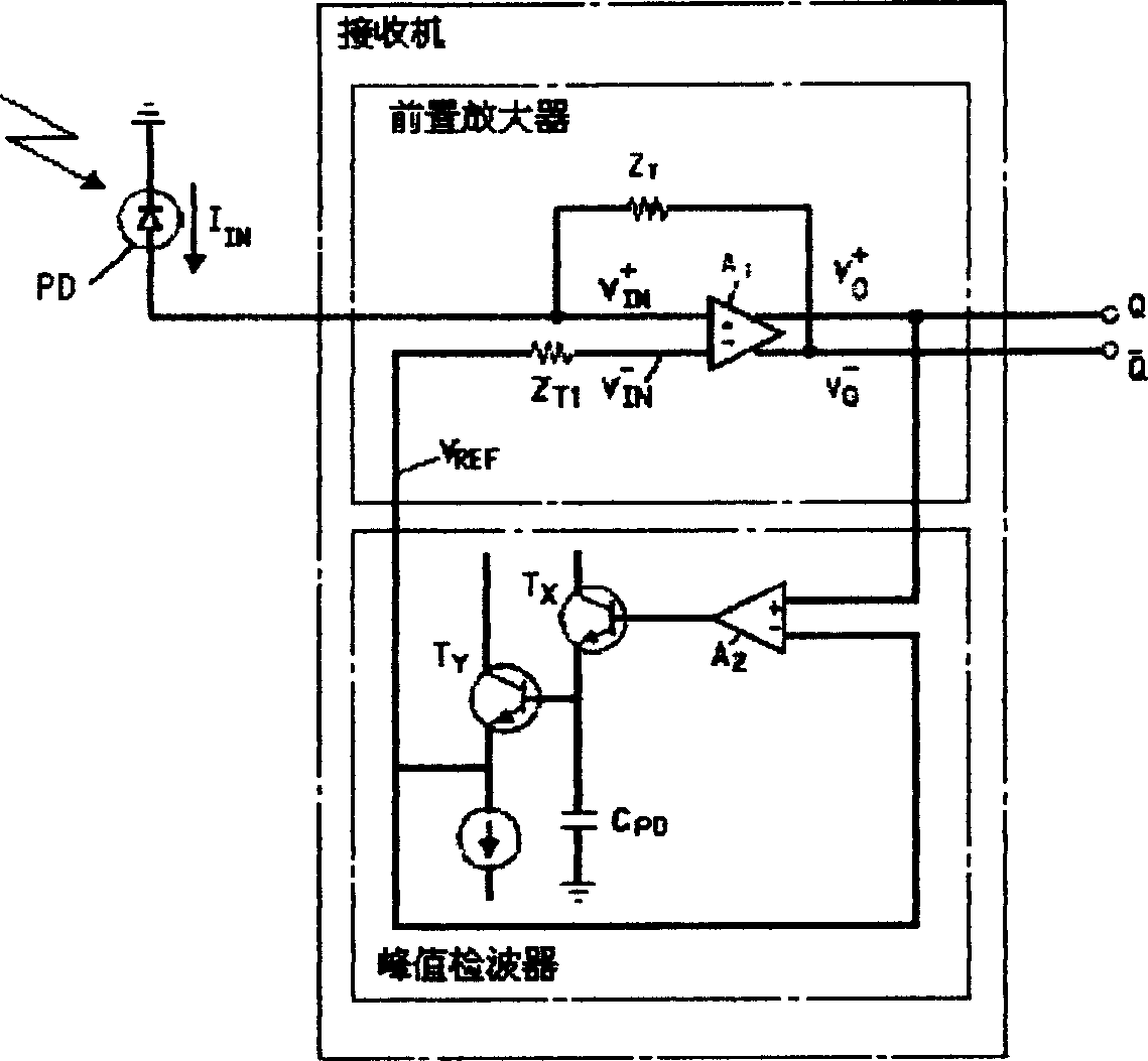
technical field [0001] The invention belongs to the field of optical fiber communication, and is used for receiving 155Mb / s (and lower rate) uplink optical signals by an office terminal (OLT) in an ATM passive optical network (APON), in particular a burst mode optical receiver. Background technique [0002] In the ATM passive optical network, each optical network unit (ONU) sends an uplink data packet optical signal to the central office in the form of time division multiple access (TDMA). Since the distance from each ONU to the OLT is not equal, the transmission loss in the optical fiber is also different. . The optical power of each data packet received by the OLT is different, which is one of the main characteristics of the burst mode optical signal. In the U.S. patent (5025456) published in 1991, described a burst mode optical receiver ( figure 1 The principle block diagram of the optical receiver in the ATC mode is shown), and there are already in...

Claims


Application Information

Patent Timeline
IPC IPC(8): H04B10/69
Inventor 陈伦裕
Owner WUHAN TELECOMM DEVICES
Learn More