
Pseudo-random number generator

A pseudo-random number and generator technology, applied in random number generators, instruments, electrical digital data processing, etc., can solve the problems of not being able to provide randomness, pseudo-random number sequence or pseudo-random number generation logic identification being vulnerable

Inactive Publication Date: 2004-10-06
NEC ELECTRONICS CORP
View PDF1 Cites 16 Cited by
  • Summary
  • Abstract
  • Description
  • Claims
  • Application Information

AI Technical Summary

Problems solved by technology

Therefore, although the pseudo-random number generator described in Japanese Patent No. 2937919 improves randomness over a configuration with a fixed shift clock, it still cannot provide sufficiently high randomness because the pseudo-random number sequence or The identification of pseudo-random number generation logic is highly vulnerable

Method used


Image

  • Pseudo-random number generator
  • Pseudo-random number generator
  • Pseudo-random number generator

Examples


Embodiment Construction

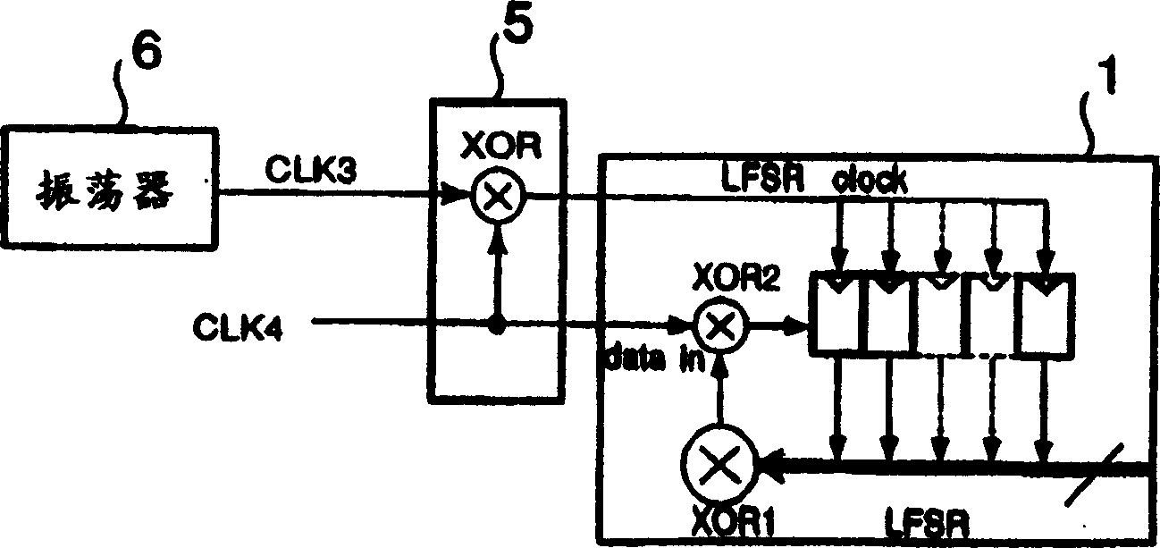
[0026] Such as figure 2 As shown, the pseudo-random number generator according to the present invention includes: LFSR1; signal generator 2, used to generate a shift clock (LFSR clock) and predetermined input data (datain) for operating LFSR1; access controller 3, used to control reading of random numbers generated by LFSR1; and writing circuit 4 for writing data supplied from the outside into each register of LFSR1. In addition, the pseudo-random number generator according to the present invention also includes a Pre-SEED circuit 5 for generating a Pre-SEED according to which the initial value (SEED) of the LFSR 1 is defined at the reset time immediately after power-on, Such as image 3 shown.

[0027] figure 2 and 3 The structure of the pseudo-random number generator according to the invention is shown in two parts in order to explain its operation, which is described below, wherein, figure 2 shows the structures associated with normal operation, image 3 The structure...


PUM


Abstract

A pseudo-random number generator comprises a linear feedback register for generating pseudo-random numbers; and a signal generator for generating a shift clock for operating a linear feedback register and predetermined input data. The linear feedback register has a plurality of registers connected in series, a first logical operation circuit for taking logical operation of output data from predetermined registers to deliver the result thereof, and a second logical operation circuit for taking logical operation of input data supplied from the outside and output data of the first logical operation circuit to supply the result thereof to any one of the registers.

Description

technical field [0001] The present invention relates to a pseudo-random number generator, which uses a linear feedback shift register (hereinafter referred to as "LFSR") to generate pseudo-random numbers. Background technique [0002] Although random numbers have traditionally been used in encryption algorithms and the like, pseudo-random numbers, which are easier to generate than random numbers, tend to be used more frequently because they are easy to manipulate and process. [0003] Pseudo-random number generators for generating pseudo-random numbers generally employ LFSRs to generate random numbers with long periods. The LFSR includes a plurality of series-connected registers, and an exclusive OR logic circuit (hereinafter referred to as an XOR circuit), wherein output data of a predetermined register is fed back to the first register through the XOR circuit. Since the XOR circuit is provided in a feedback path, the LFSR generates random numbers with a longer period. ...

Claims


Application Information

Patent Timeline
Patent Type & Authority Applications(China)
IPC IPC(8): G06F7/58G09C1/00H03K3/84
CPCG06F7/582
Inventor 岛崎真也
Owner NEC ELECTRONICS CORP
Learn More