Double deck elevator

A technology of double-deck elevators and target floors, which is used in elevators, agriculture, elevators and other directions in buildings, which can solve the problems of increased speed changes, large speed changes, and increased equipment costs.

Inactive Publication Date: 2004-09-29
TOSHIBA ELEVATOR KK
View PDF1 Cites 7 Cited by
  • Summary
  • Abstract
  • Description
  • Claims
  • Application Information

AI Technical Summary

Problems solved by technology

[0008] However, according to the conventional method described above, the car spacing is adjusted during deceleration from the start of the elevator deceleration until the elevator stops, and if the adjustment distance between the cars is large or the elevator deceleration period is short, the speed change at the time of the adjustment operation is large
That is, because it is necessary to adjust the car pitch corresponding to a target floor in a short period of time during deceleration, figure 2 The speed change between the shown times t1 and t2 increases and this speed change makes the occupant feel out of tune and therefore uncomfortable
[0009] In addition, adjusting the car spacing in a short time during deceleration requires a large-power car drive, resulting in increased equipment costs

Method used


Image

  • Double deck elevator
  • Double deck elevator
  • Double deck elevator

Examples


no. 1 example

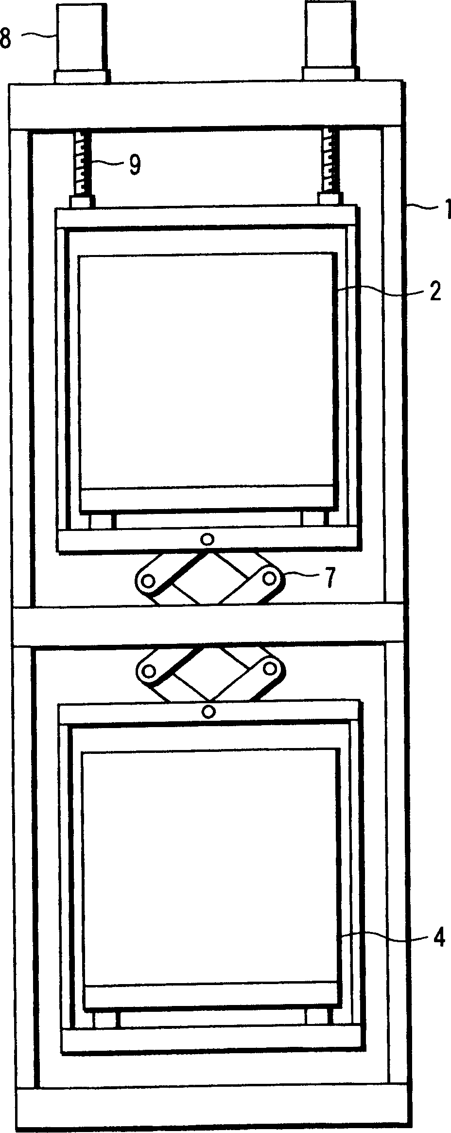
[0022] image 3 is a schematic diagram showing the structure of a double-deck elevator according to the first embodiment of the present invention. The elevator includes a car frame 1 and upper and lower cars 2 and 4 arranged in the car frame 1 .

[0023] The upper car 2 and the lower car 4 are installed on the car frame 1 , and either or both of the upper car 2 and the lower car 4 have a car driving device 10 . For example, in image 3 Among them, the lower car 4 has a car drive 10 . The car drive 10 includes a guide roller 5 and an actuator 6 . If the actuator 6 of the car driving device 10 is driven, the lower car 4 is lifted / lowered by the guide roller 5, thereby changing the distance between the upper car 2 and the lower car 4 . Hereinafter, the car driven by this car driving device 10 is referred to as a "moving car". According to the present invention, the structure of the car driving device 10 is not limited to any specific structure.

[0024] The car frame 1 on w...

no. 2 example

[0069] Next, a second embodiment of the present invention will be described.

[0070] Figure 7 is a schematic diagram showing the structure of a double-deck elevator according to the second embodiment of the present invention. In this second embodiment, with the structure of the first embodiment ( image 3 ) In comparison, the car position control device 16 and the memory 17 are included in the winch control device 15 .

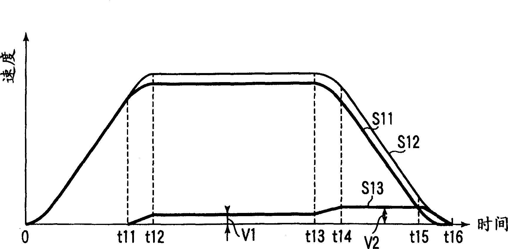
[0071] In other words, the winch control device 15 includes a correcting car position control device 16 and a memory 17 , and the winch control device 15 sends a control command to the winch machine 13 and a control command to the car driving device 10 . The memory 17 stores data on the velocities V1 and V2 calculated from the inter-layer information of each layer or its pre-stored inter-layer information.

[0072] With this configuration, the car drive device 10 is controlled as follows, similarly to the first embodiment. The hoist control device 15 sta...


PUM


Abstract

A double deck elevator comprises a winding machine which lifts up / down a cage frame loaded with two cages in a vertical direction, a cage driving unit which changes a relative distance between upper and lower cages, and a cage position controller which starts an inter-cage distance adjustment operation of the cage driving unit almost at the same time when the winding machine is shifted from an acceleration operation to a constant velocity operation, and changes an operating velocity of the inter-cage distance adjustment operation corresponding to a destination floor almost at the same time when the winding machine changes from the constant velocity operation to a deceleration operation after the destination floor is determined, whereby completing the inter-cage distance adjustment operation almost at the same time when the winding machine stops.

Description

technical field [0001] The present invention relates to a double-deck elevator in which two cars are connected vertically, and more particularly to a double-deck elevator having a car spacing adjusting mechanism capable of adjusting the spacing between the cars during elevator operation. Background technique [0002] In a high-rise building or the like, in order to improve the space efficiency of the building, a double-deck elevator in which two cars are vertically arranged on two floors is used as a transportation means for vertical transportation in the building. in such as figure 1 In the double-deck elevator shown, this has a car that adjusts the distance between the cars by using a crank mechanism 7 to move the upper and lower cars 2, 4 in the car frame 1 in opposite directions. The types of spacing adjustment mechanisms are well known. exist figure 1 In the shown type, the upper car 2 and the lower car 4 are installed on the crank mechanism 7 installed in the middle...

Claims


Application Information

Patent Timeline
Patent Type & Authority Applications(China)
IPC IPC(8): B66B1/06B66B1/14B66B1/24B66B1/42B66B11/02
CPCB66B1/30B66B1/285B66B1/42B66B11/0095Y10S187/902B66B1/425B66B11/022B66B1/18
Inventor 藤田善昭冈本正胜
Owner TOSHIBA ELEVATOR KK
Why Eureka
Try Eureka