
High-volage transmitting-line multiple-path high-precision GPS single-end fault positioning method and apparatus

A high-voltage transmission line, fault location technology, applied in the fault location, information technology support system and other directions, can solve the problems of low location accuracy, unreliability, heavy maintenance workload, etc., to achieve high fault location accuracy, reduce occupation, reduce equipment effect of input

Active Publication Date: 2004-09-15
WUHAN UNIV
View PDF0 Cites 22 Cited by
  • Summary
  • Abstract
  • Description
  • Claims
  • Application Information

AI Technical Summary

Problems solved by technology

[0006] (1) Low positioning accuracy: The error of the traveling wave method is generally 500-1000 meters, and the error of the impedance method is generally 3-5% of the total length of the line;
[0007] (2) The reliability is not high: traveling wave ranging is difficult to catch the wave head when the fault is close, and the dead zone is large; the error of the impedance method increases with the length of the fault line. Unreliable;
[0008] (3) A substation generally requires multiple sets of fault location devices, which are costly and require heavy maintenance workload;
[0009] (4) The double-ended fault location device needs to install corresponding equipment at the opposite end, which needs to occupy the communication channel, and it is difficult to debug and maintain

Method used


Image

  • High-volage transmitting-line multiple-path high-precision GPS single-end fault positioning method and apparatus

Examples


Embodiment Construction

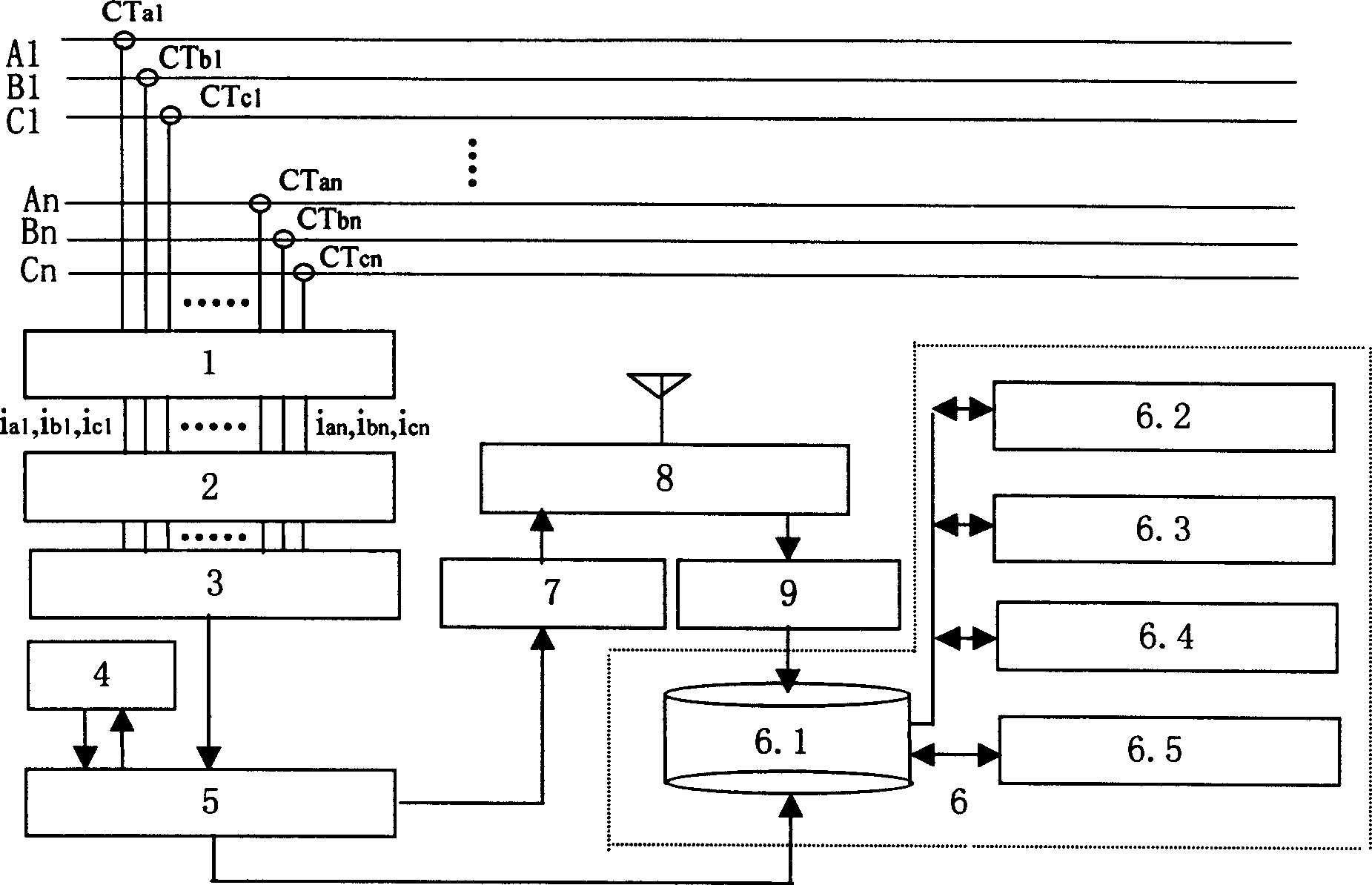
[0038] The working principle of the present invention will be further introduced in conjunction with accompanying drawing 1 below.

[0039] In accompanying drawing 1, A1, B1, C1, . . . , An,, Bn, Cn represent n three-phase high-voltage transmission lines. The input terminals of the multi-line three-phase current detection unit 1 are respectively connected to the secondary side windings of the current transformers of each line: CTa1, CTb1, CTc1, ..., CTan, CTbn, CTcn, after voltage conversion and high-impedance isolation, its output is connected to the valve The value detects the input end of the fault line identification unit 2, and completes the multi-line three-phase current detection function. Threshold detection fault line identification unit 2 detects the three-phase current i a1 , i b1 , i c1 ,..., i an , i bn , i cn and the corresponding three-phase threshold current (the minimum fault current that may cause relay protection action) i a10 , i b10 , i c10 ,..., ...


PUM


Abstract

Signals are fetched out from winding at secondary side of current transformer on each line so as to obtain detected currents in triphase after voltage conversion and isolation of high-ohmic resistor. Threshold measuring detected currents in triphase is carried out in order to determine fault lines, and functions of high-speed data correction and A / D conversion are started up. Characteristic data of defective form of traveling wave are picked up from the A / D converted data, which are labeled with time mark by high precision GPS device. Then, being sorted and matched according to lines, the labeled data are stored to memory in computer. Fault category is determined and fault distance is calculated out by using the said computer and dedicated application software to analyze and calculate characteristic data after multiple refractions and reflections in each line as well as time difference. The invention raises location accuracy, reliability, practibility and economical efficiency.

Description

technical field [0001] The invention belongs to the technical field of fault diagnosis of a high-voltage transmission network in an electric power system, and in particular relates to a multi-channel high-precision GPS single-end fault location method and device for a high-voltage transmission line. Background technique [0002] High-voltage transmission line fault location device is the main equipment for fault diagnosis of high-voltage transmission network in power system. Commonly used high-voltage transmission line fault location devices can be divided into two types from the principle point of view: [0003] (1) Impedance method: This method detects the voltage and current values ​​on one side of the line (single-ended method) or both sides (double-ended method), and calculates the equivalent impedance from the detection point to the fault point of the transmission line through mathematical methods, so that Determine the location of transmission line faults. The posit...

Claims


Application Information

Patent Timeline
IPC IPC(8): G01R31/08
CPCY04S10/522Y04S10/52
Inventor 李晓明刘经南
Owner WUHAN UNIV
Learn More